|
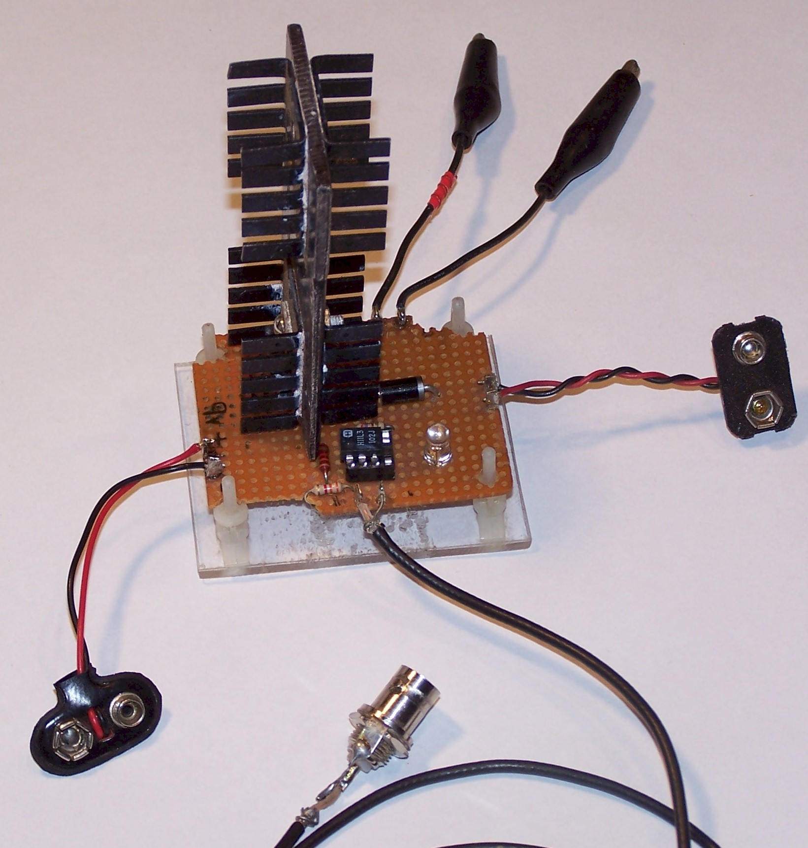
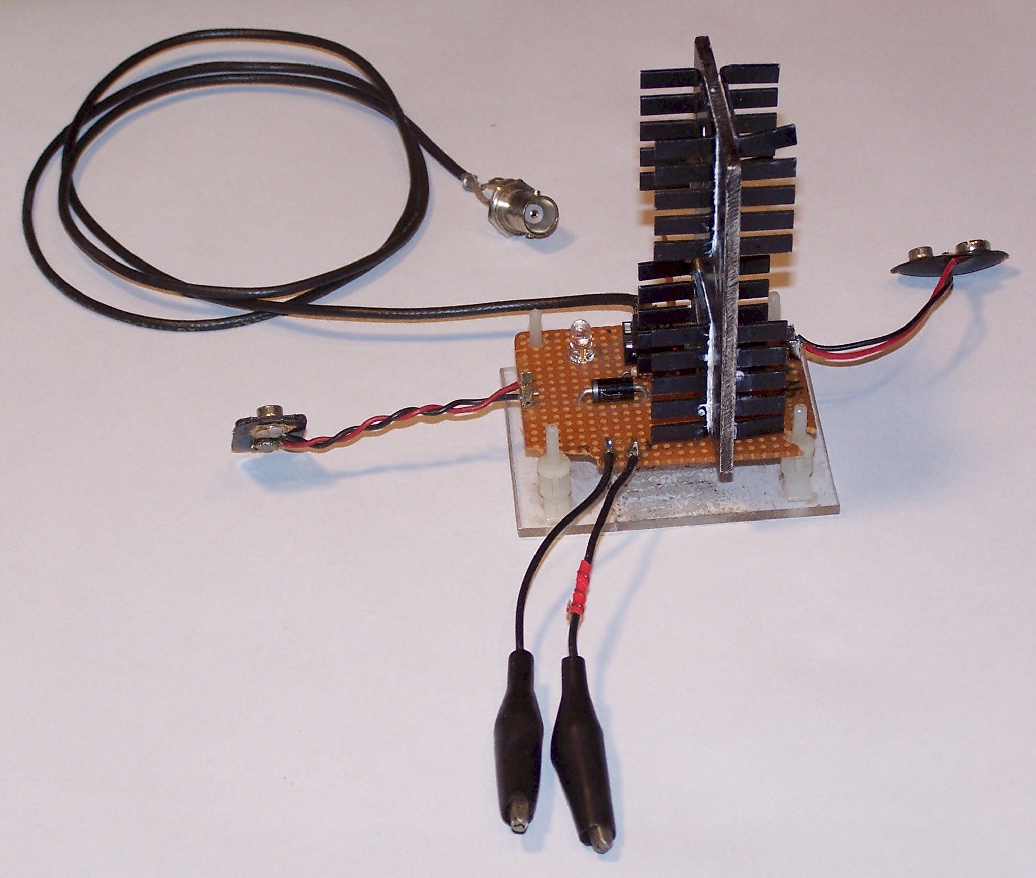
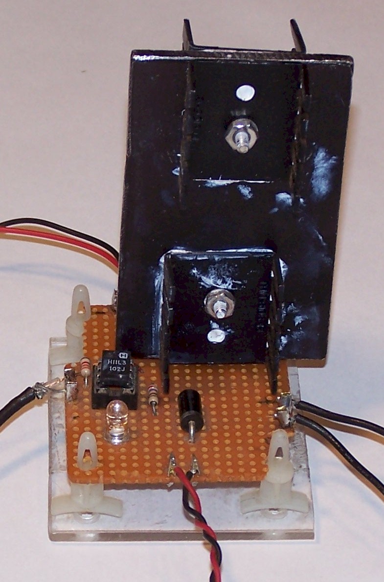
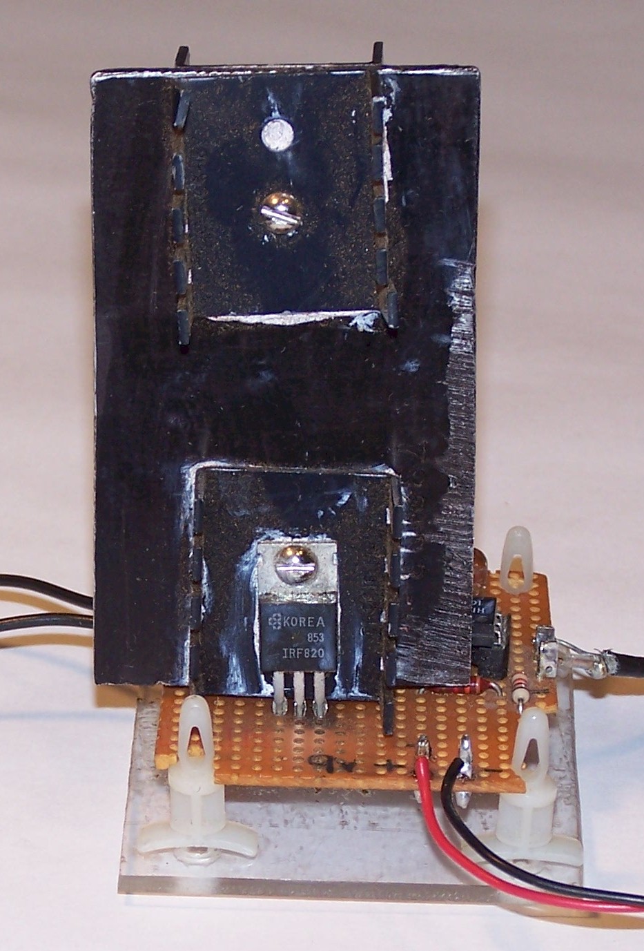
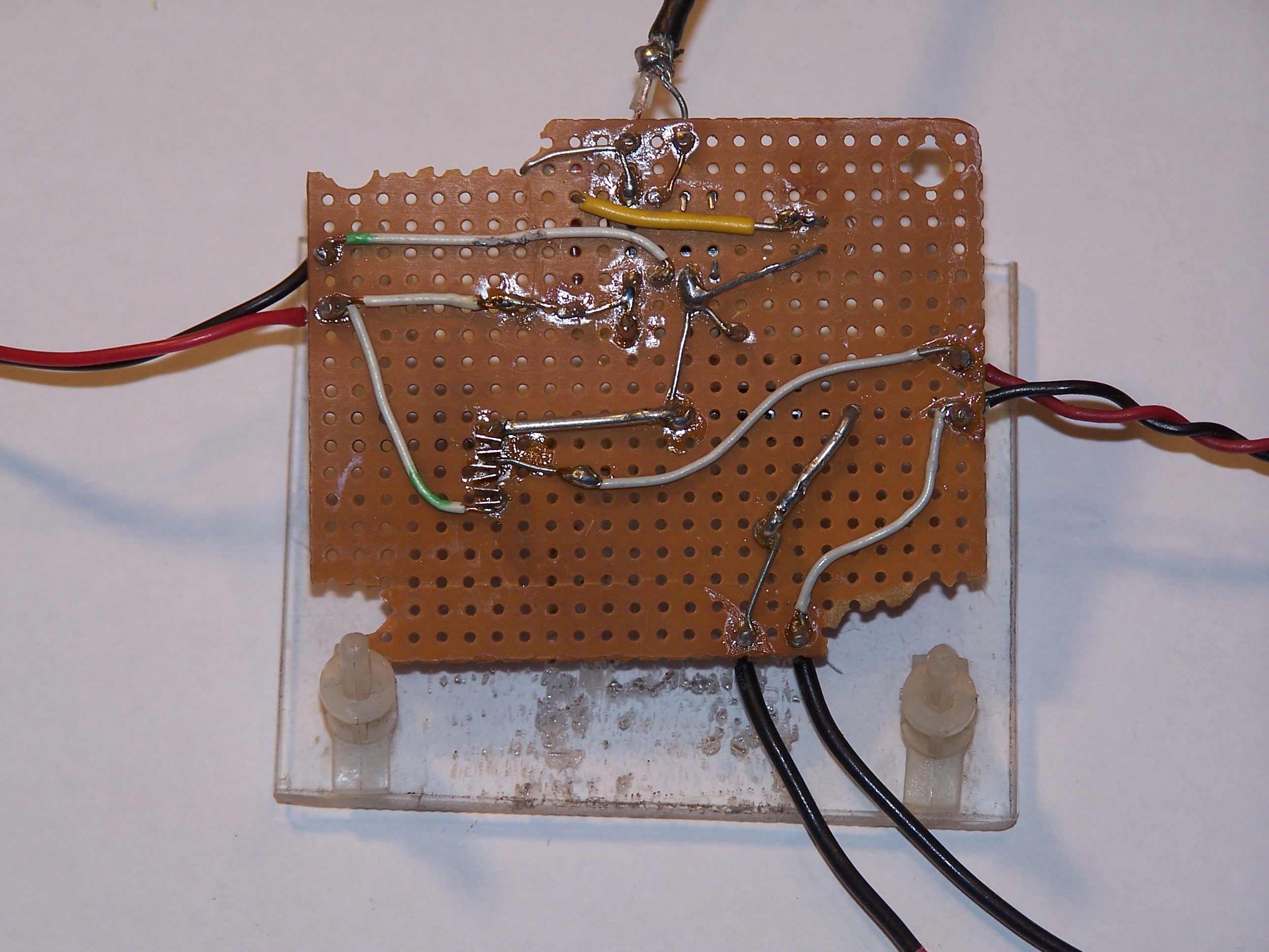
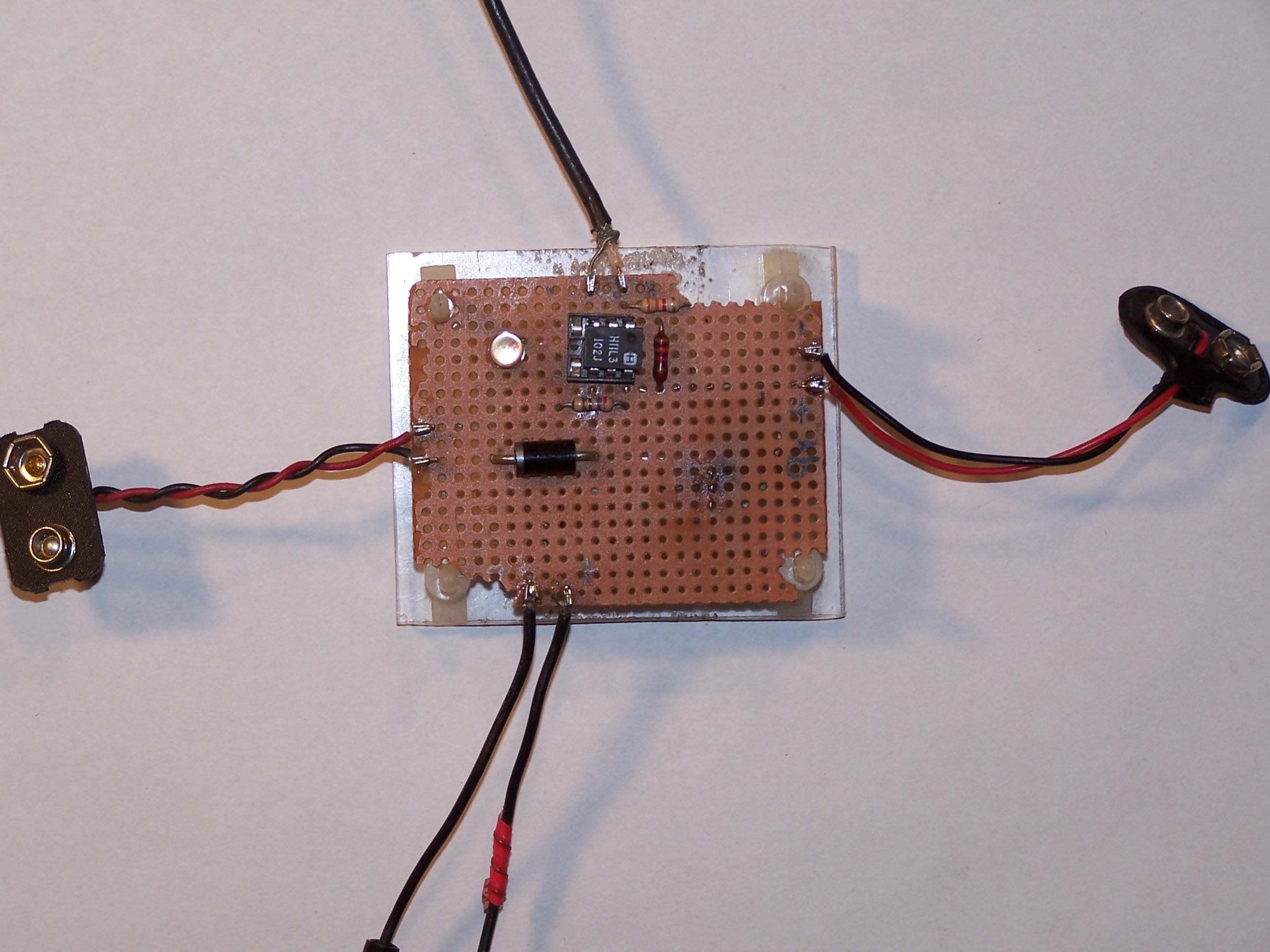
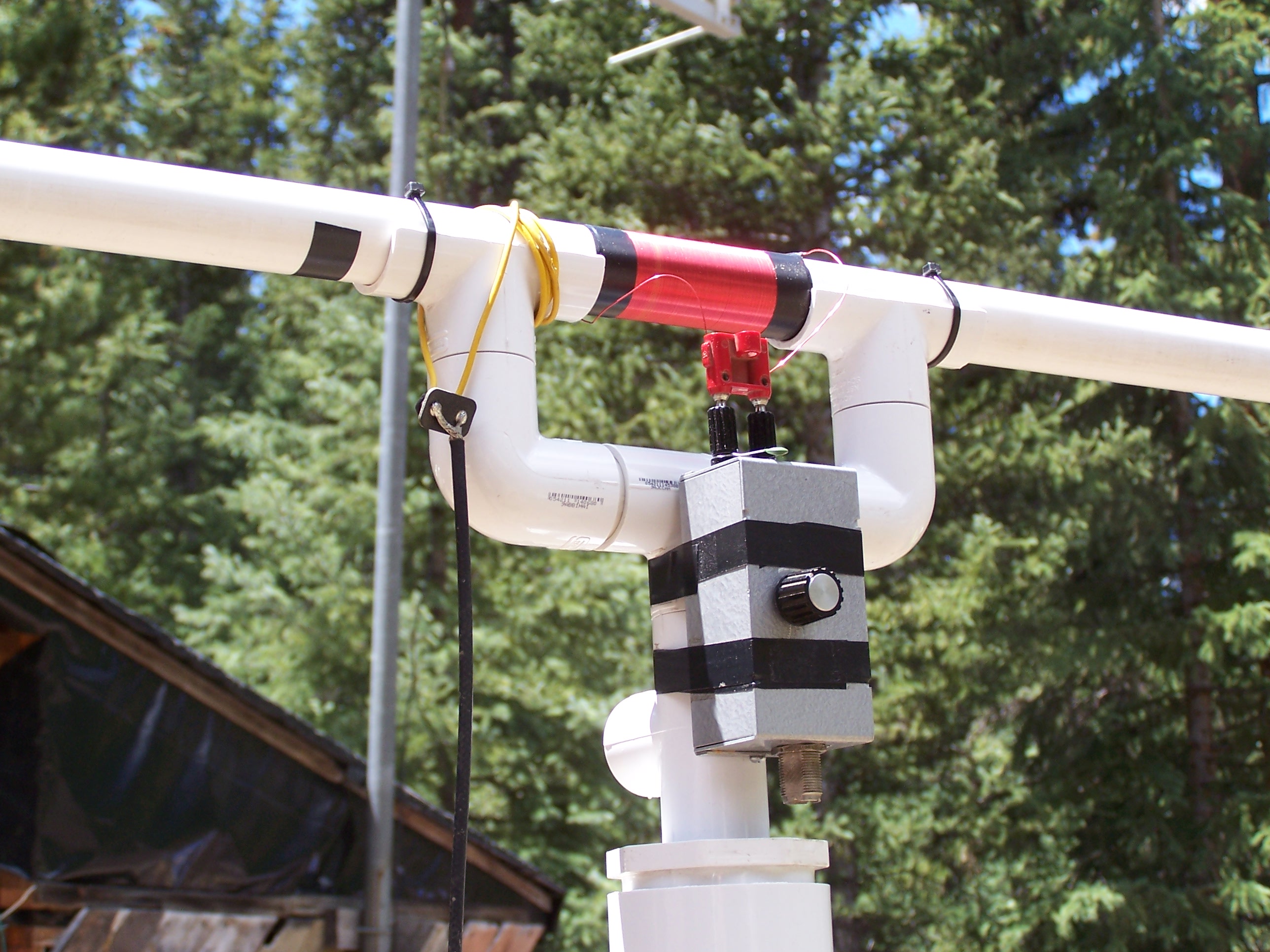
This little switch has taken quite a beating over the years, and is due for replacement. Notice that only one MOSFET is used. In operation it is connected to a D.C. power supply consisting of a single 12-volt lead acid battery or two of them connected in series. |
|
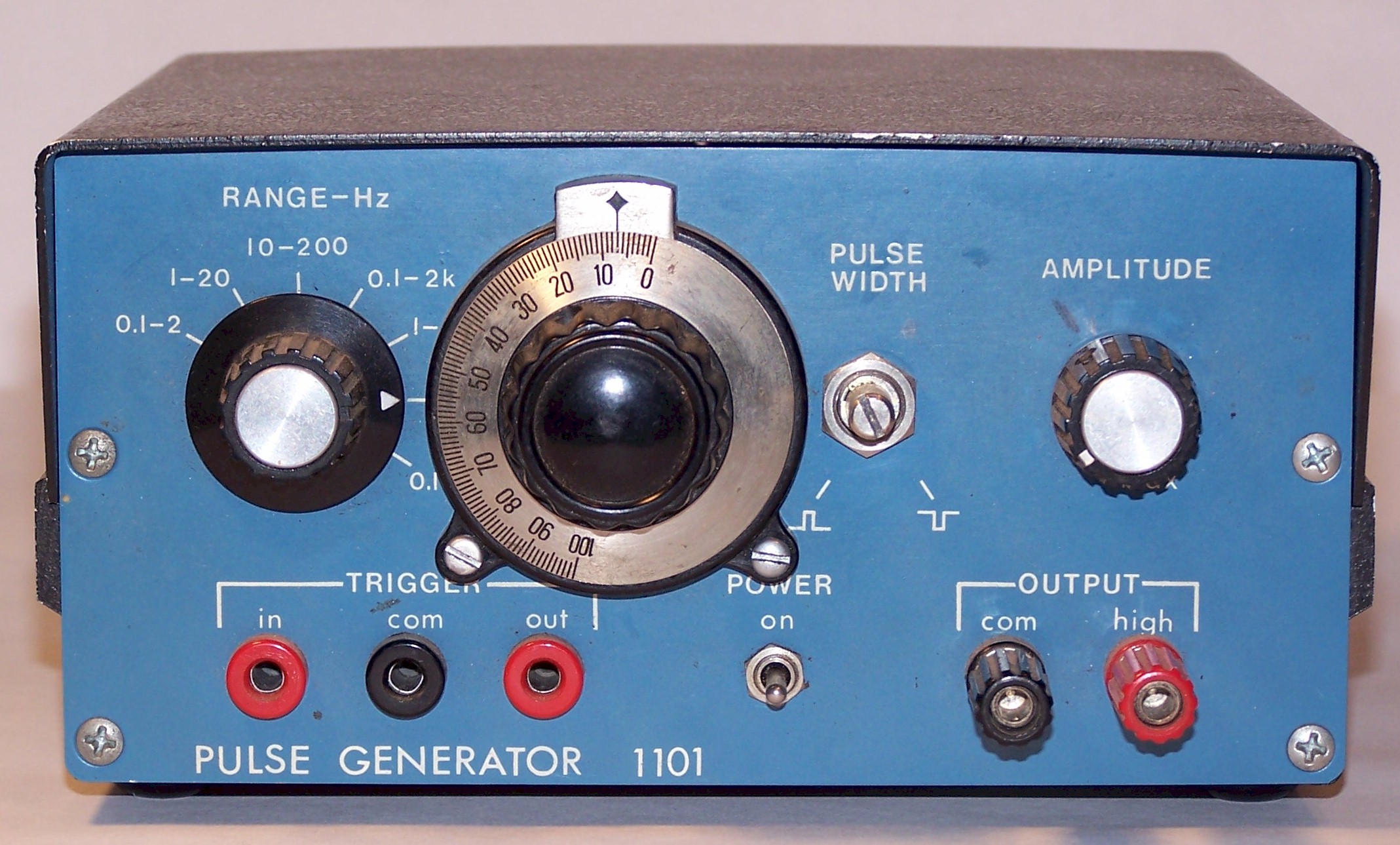
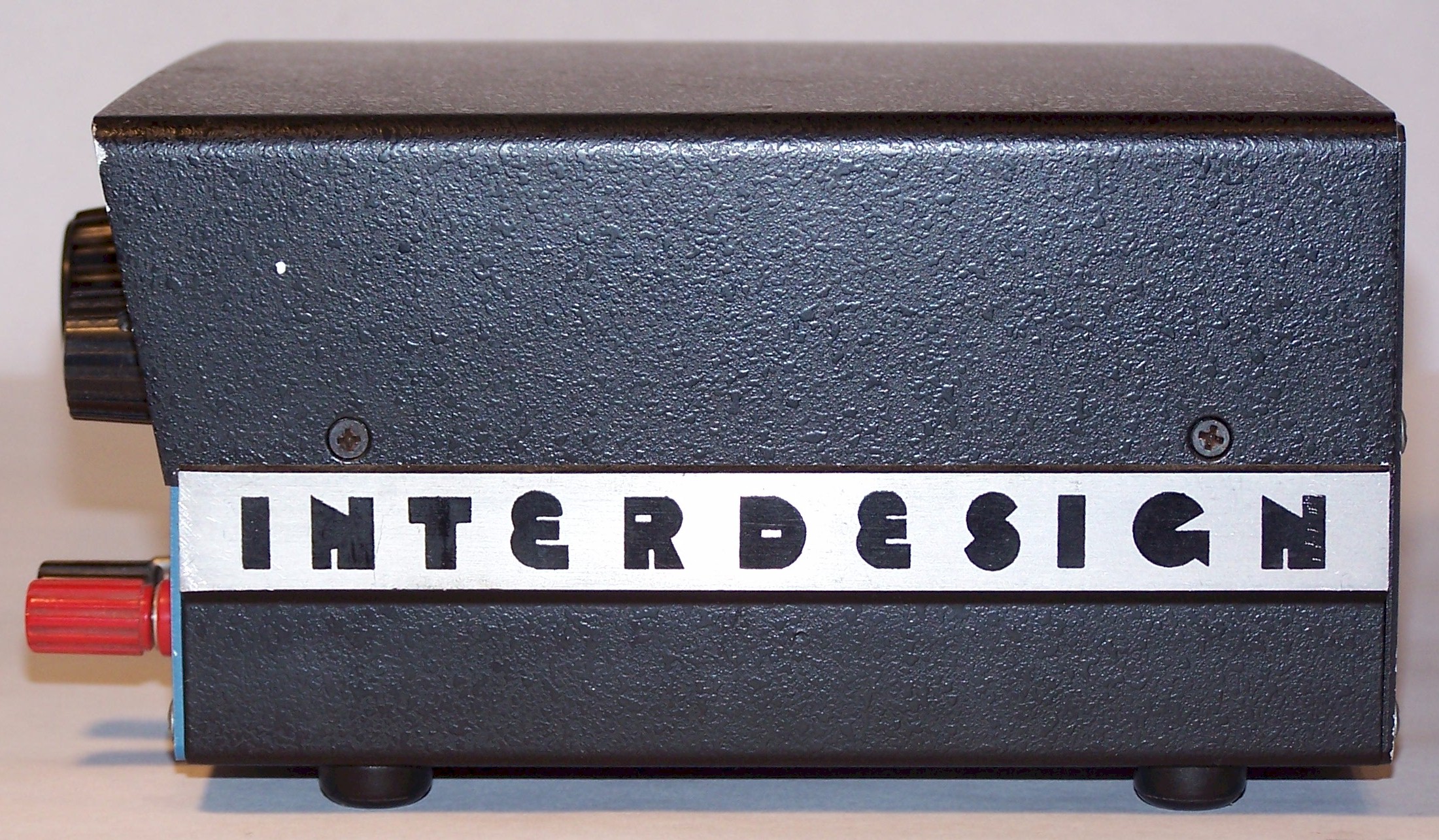
A not-so-precise pulse generator is used to drive the switch. Changing over to a self-resonant driver configuration would probably solve a slight temperature-related frequency stability problem. Alternatively, a high-precision waveform generator is now used. |

|
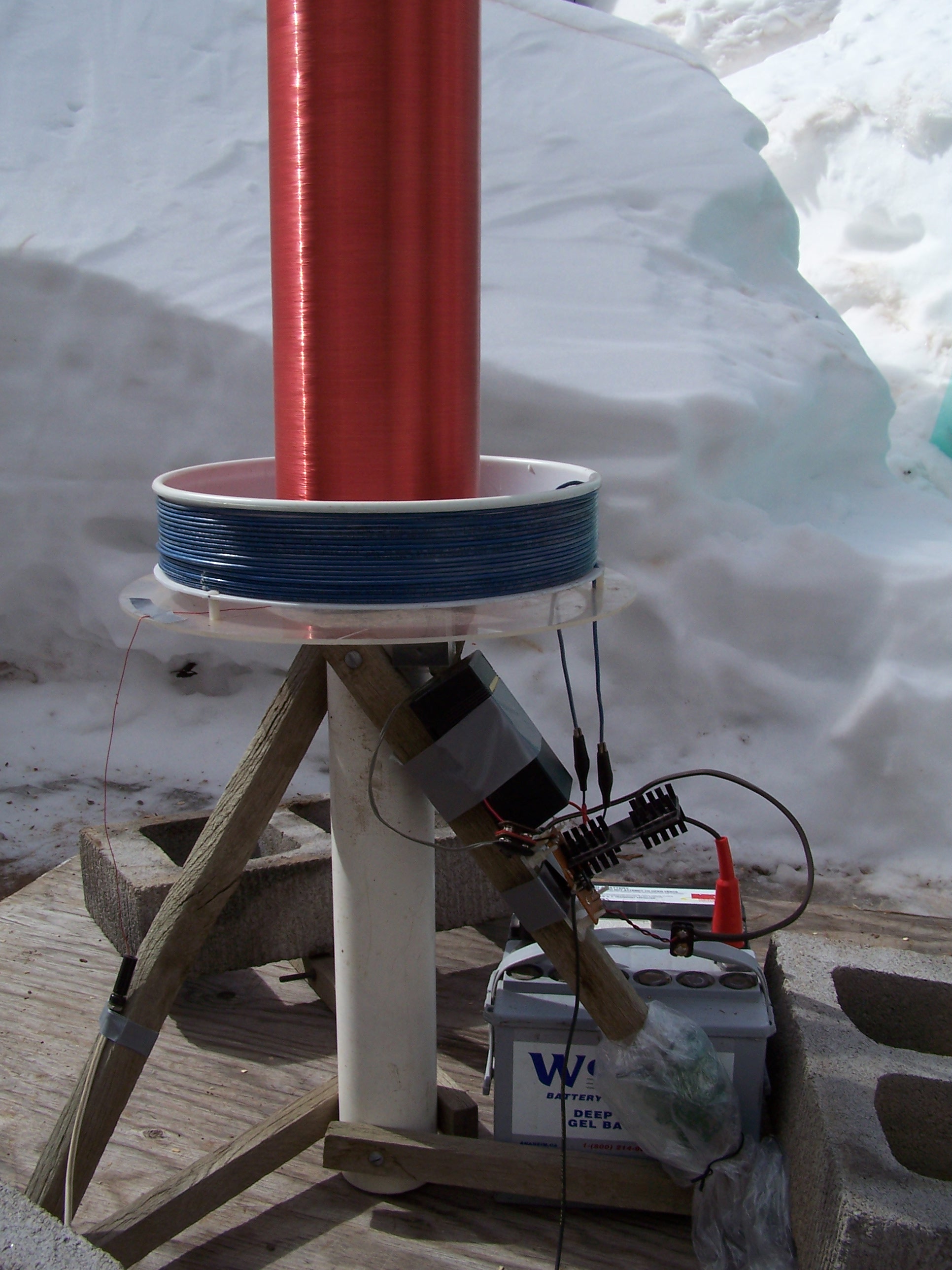
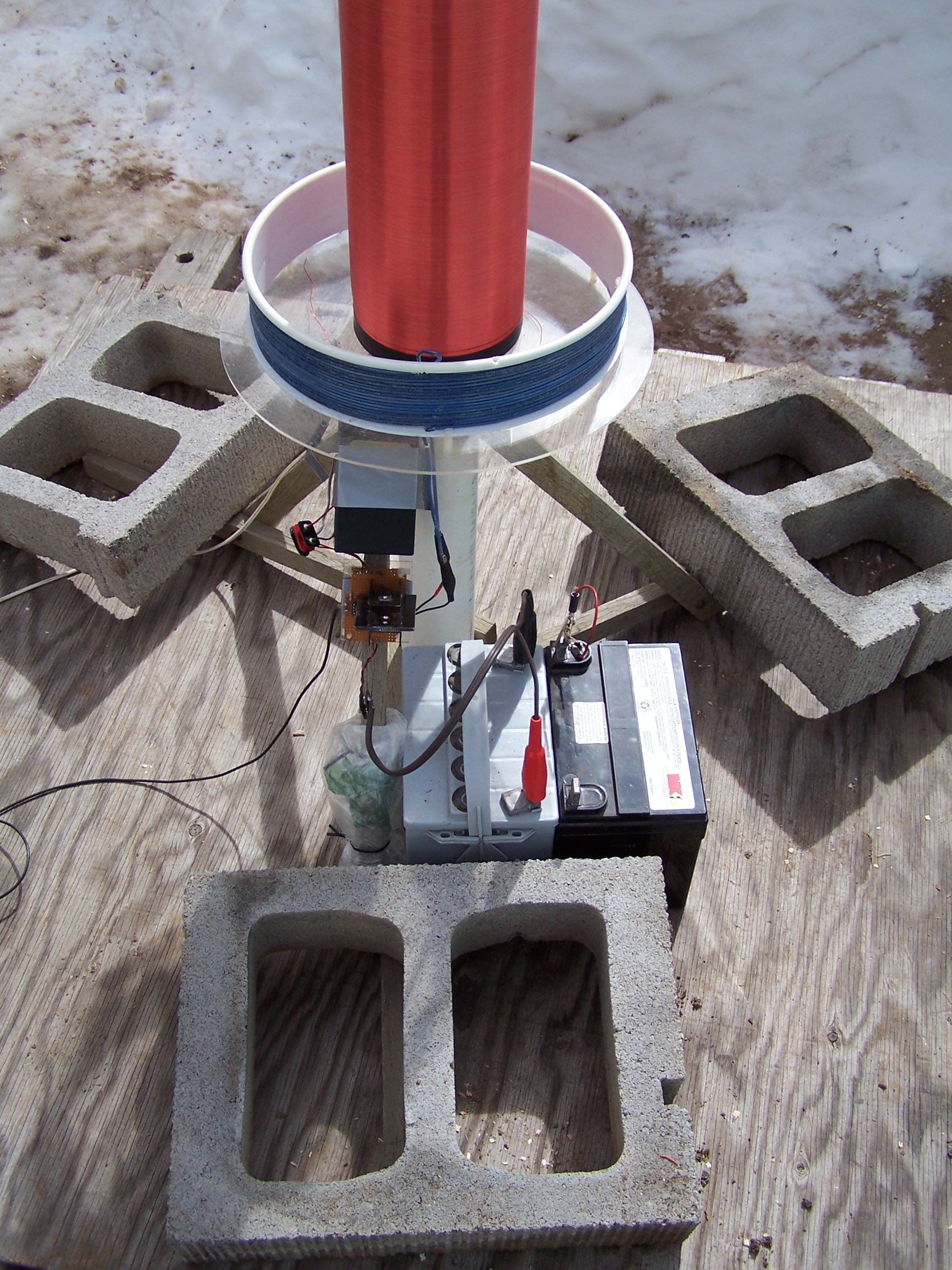
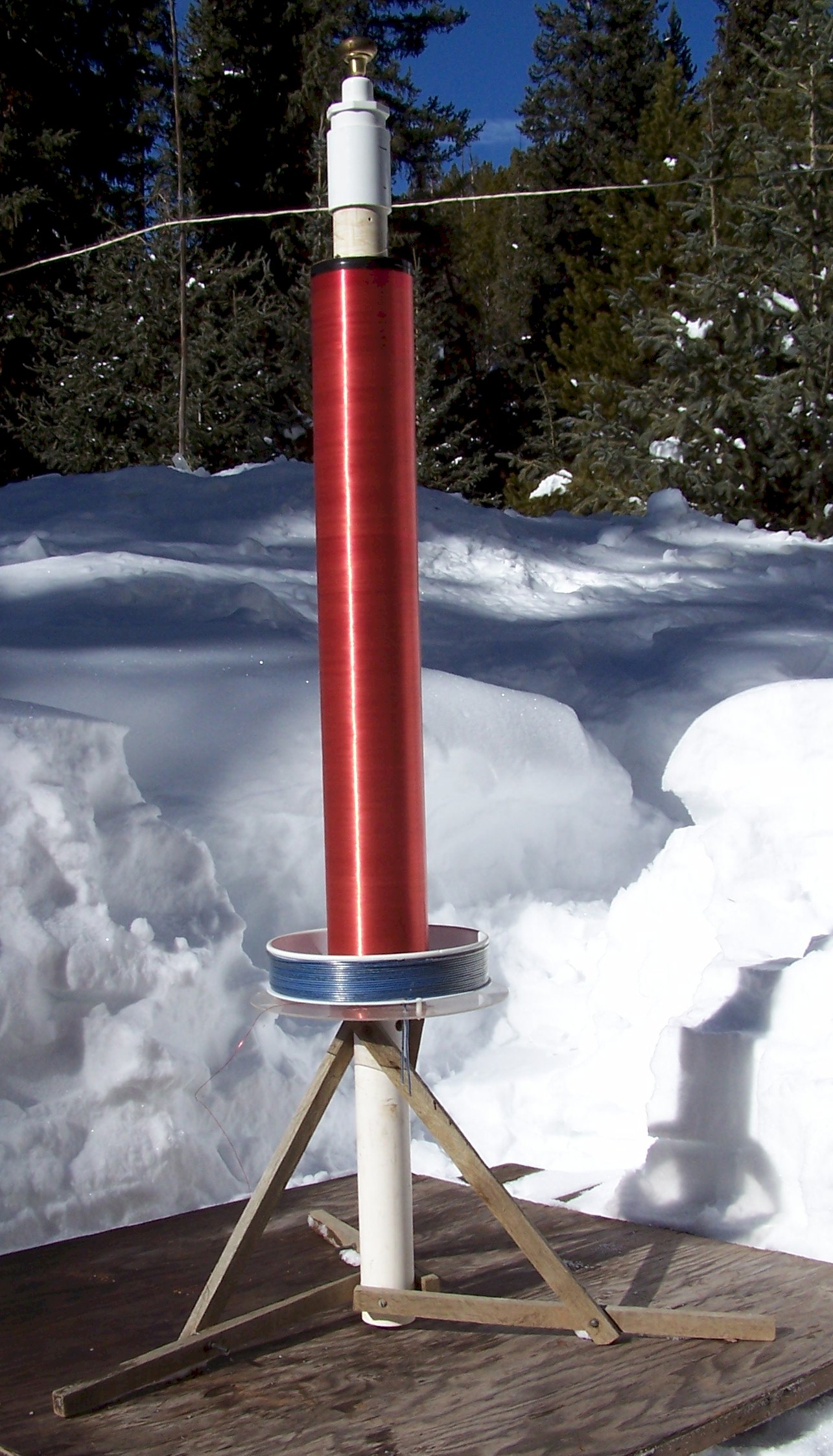
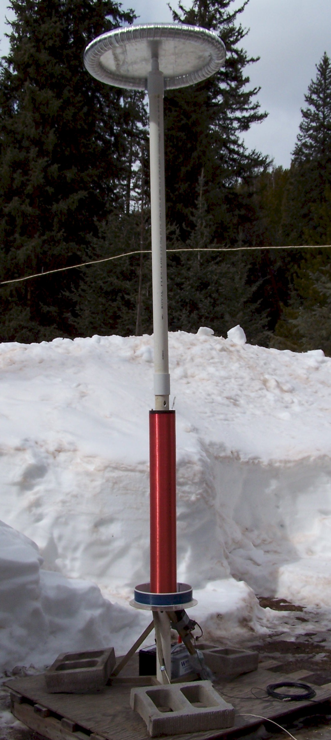
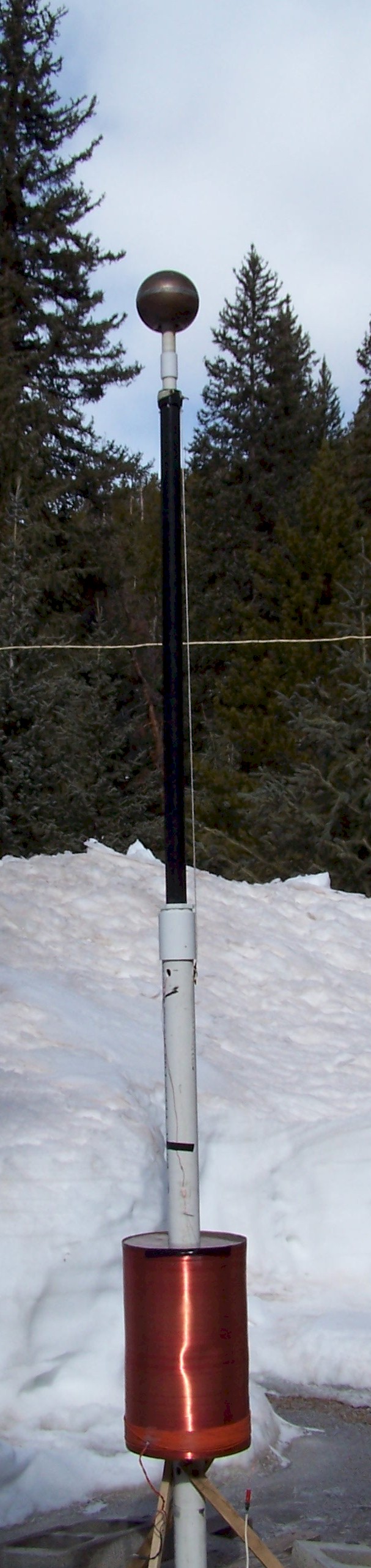
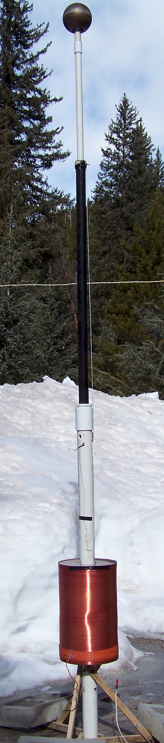
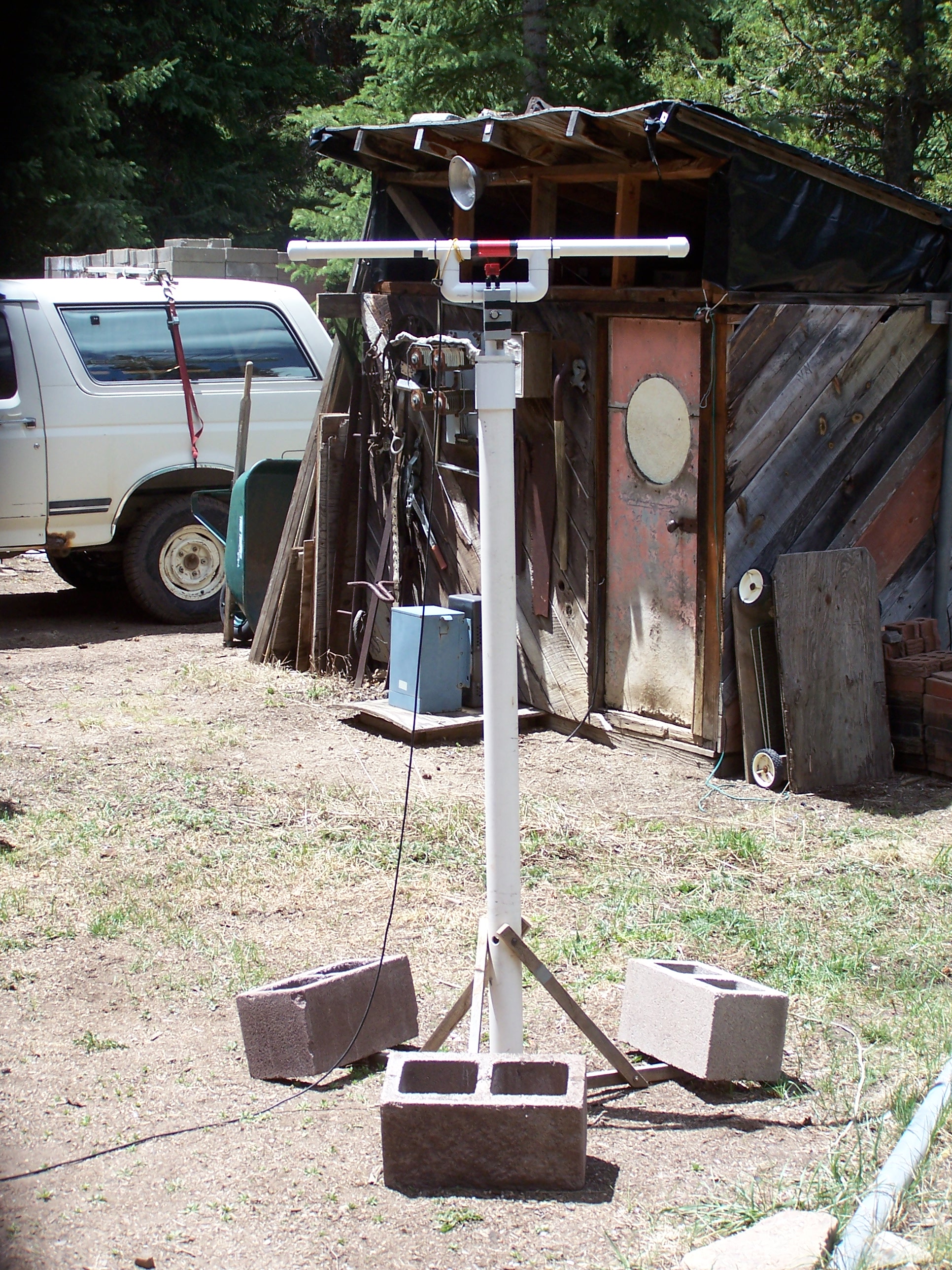
A
type-one Tesla transmitter. The resonator has a 7:1 aspect ratio,
which is the same as one of the experimental coil forms that Tesla used in Colorado Springs.
With the door-knob topload it
resonates at about 185 kHz. An elevated 23"
diameter aluminum disk brings the resonant
frequency down to about 123 kHz or lower. |
![]()
![]()
|
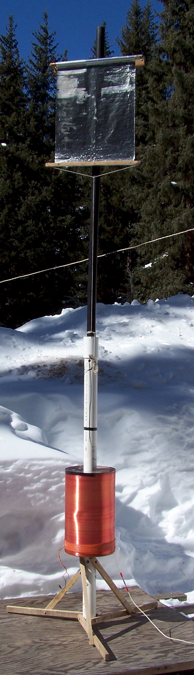
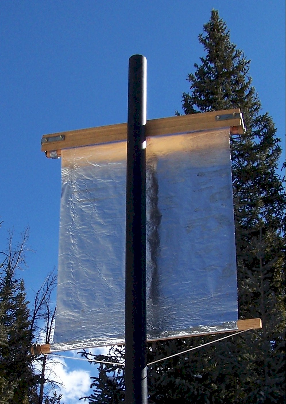
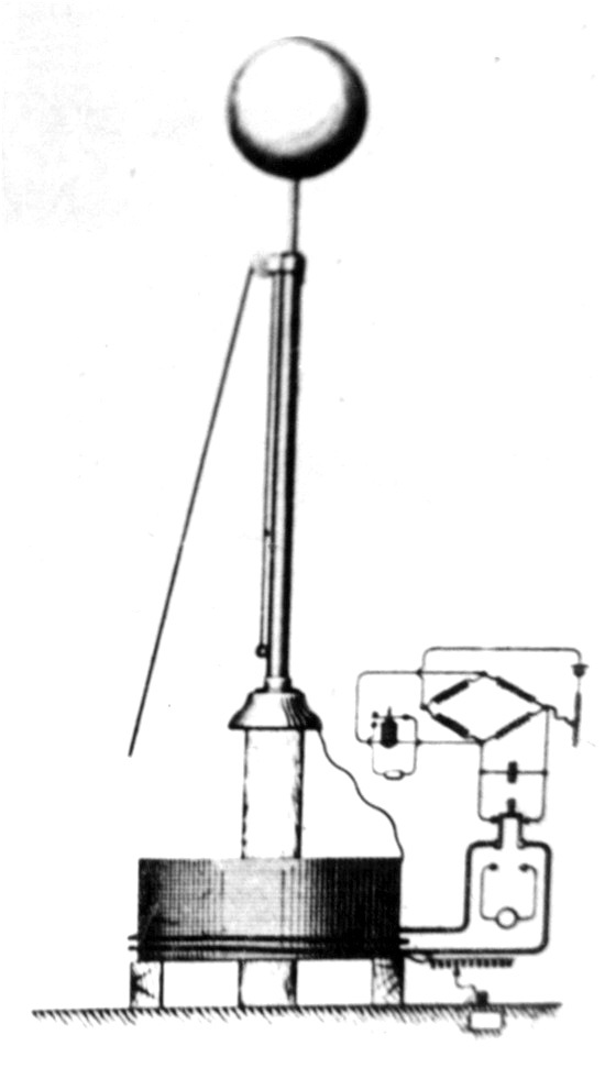
A Tesla receiving transformer
with widely-adjustable variable elevated terminal.
The terminal is not
very robust, but gives a very wide range of tuning and is particularly useful
when first configuring a transmitter-receiver pair. |
![]()


|
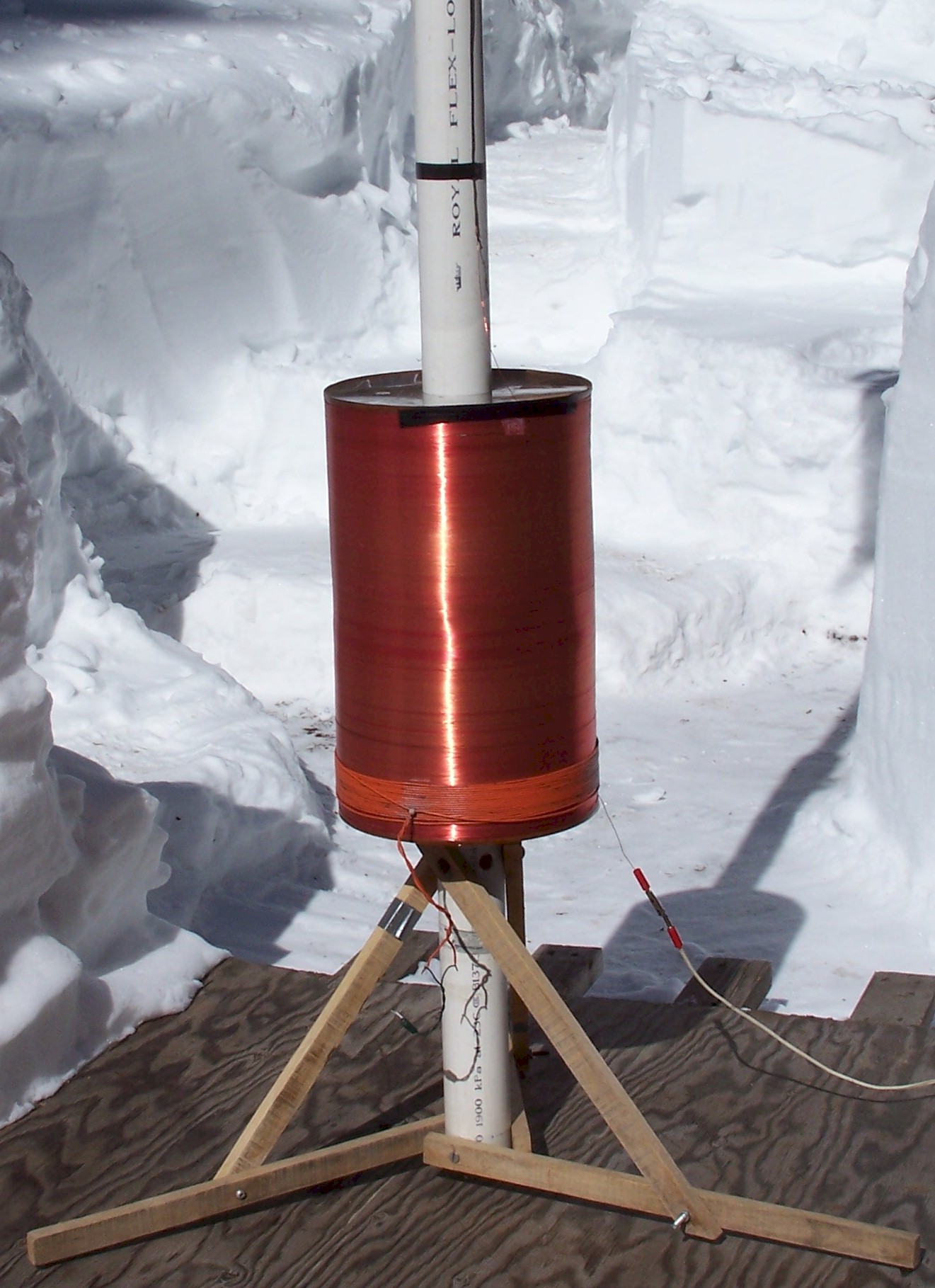
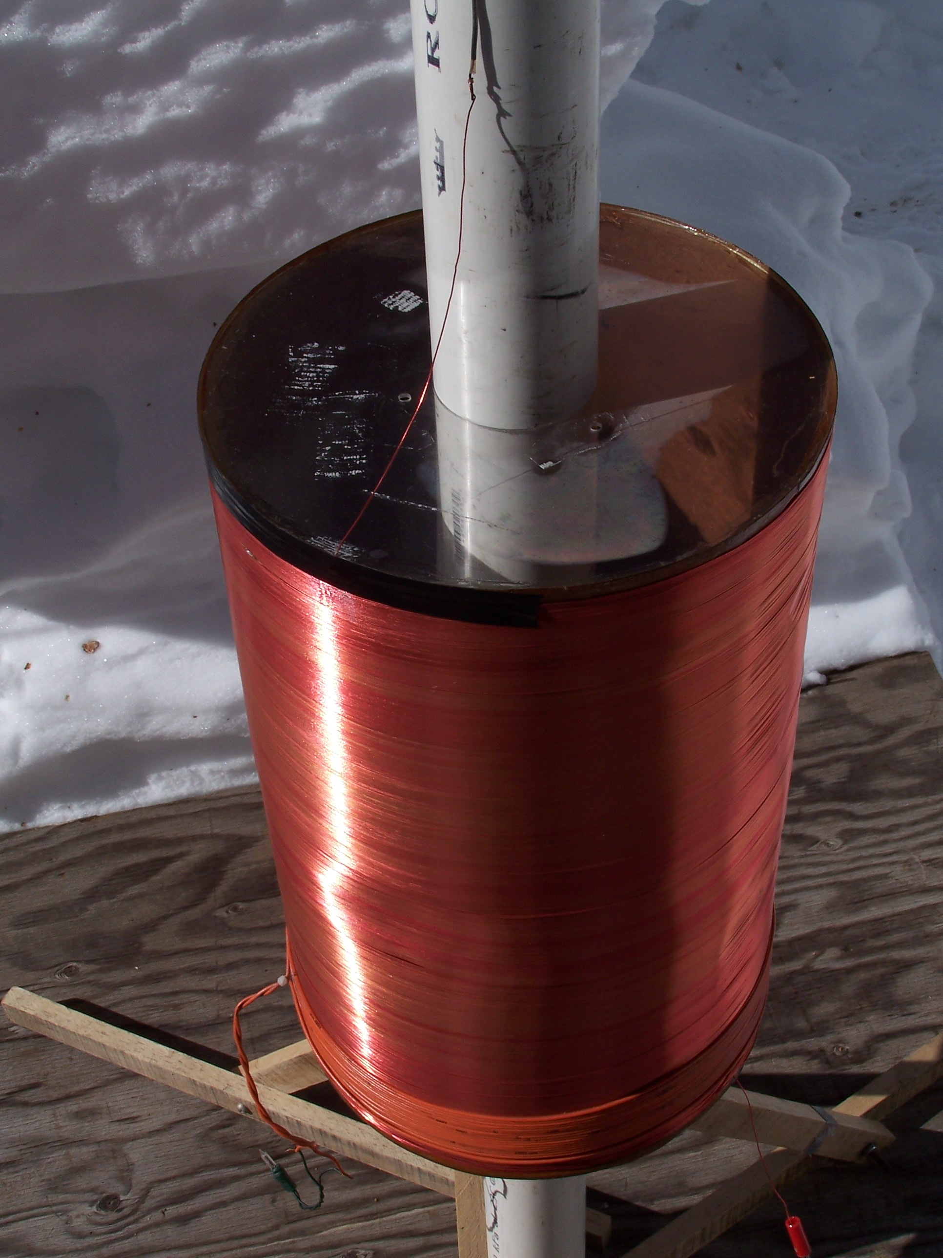
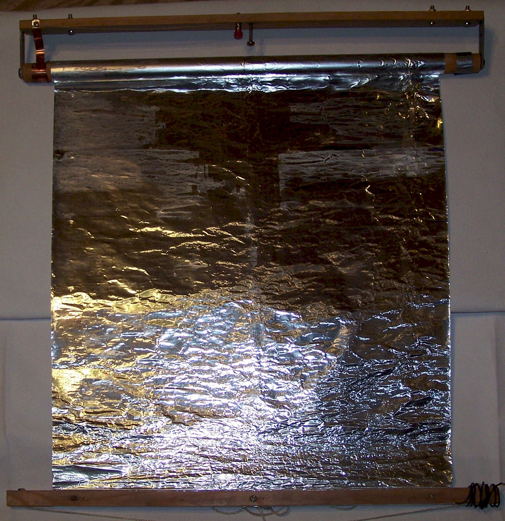
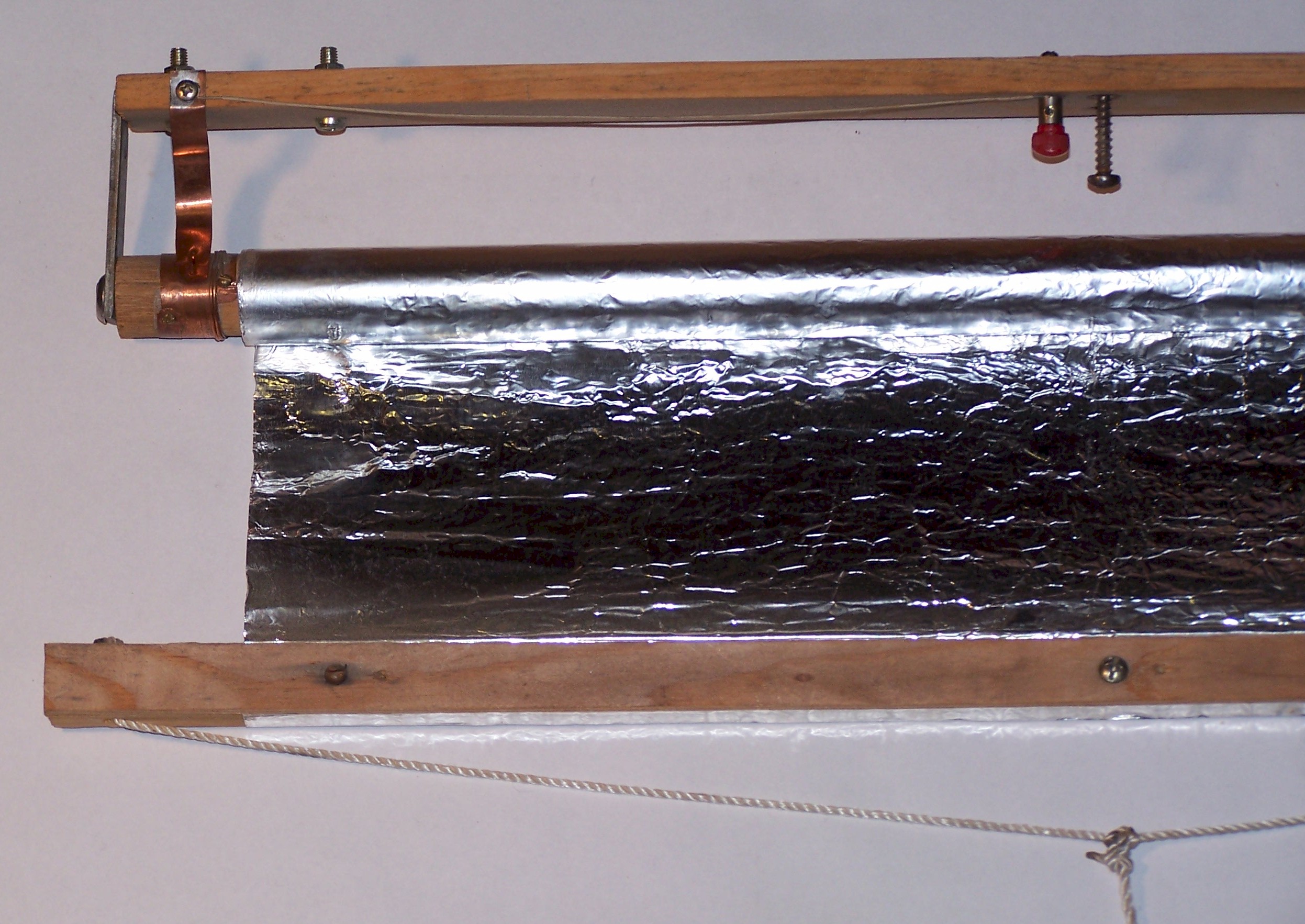
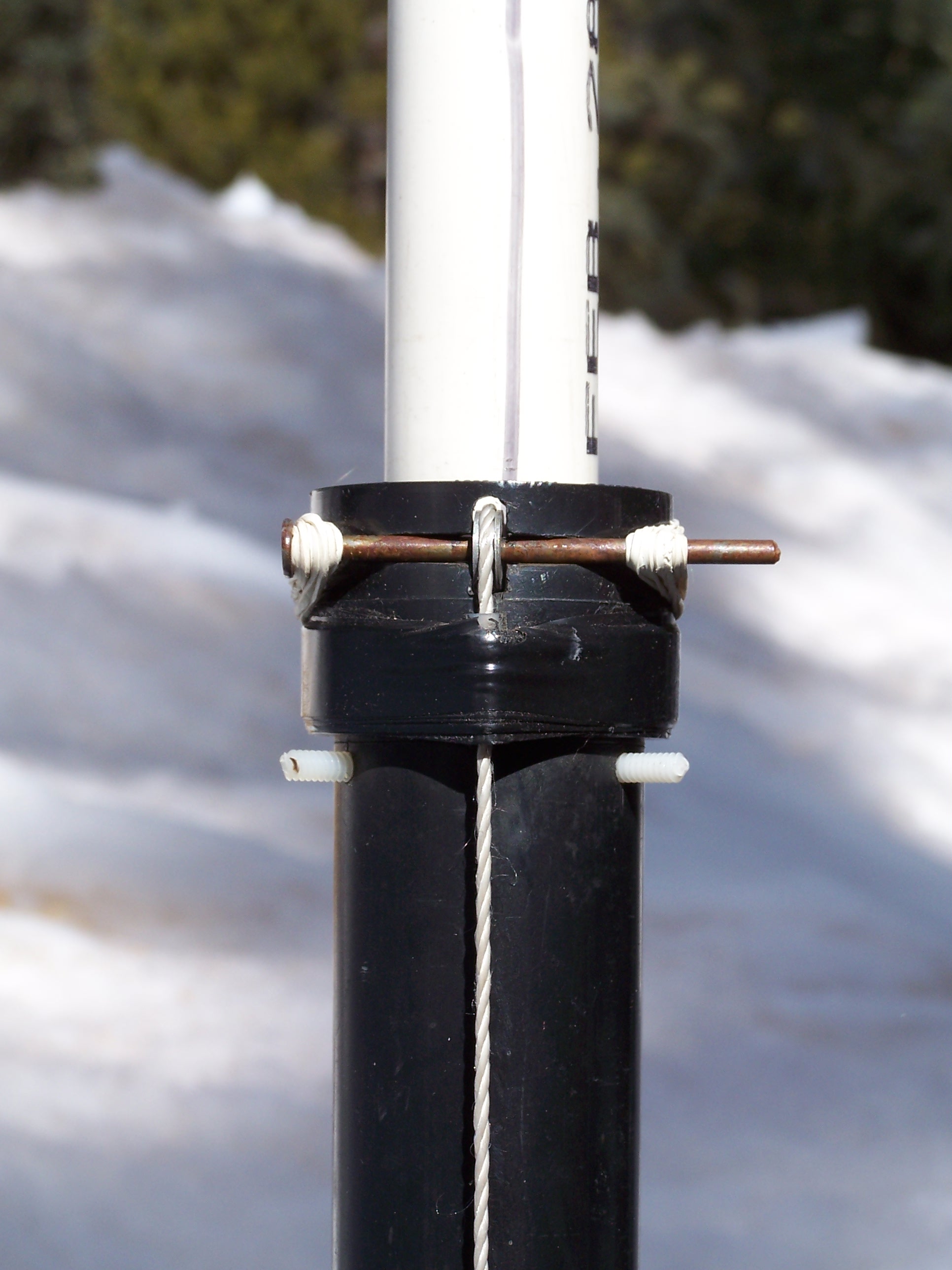
A Tesla receiving transformer
with narrowly-adjustable variable elevated terminal. The conductor
that connects the top turn of the resonator to the terminal includes a
festoon The terminal and its support structure is robust and
provides a narrow range of tuning. It is particularly useful
for the fine-tuning of both transmitters and receivers. |
|
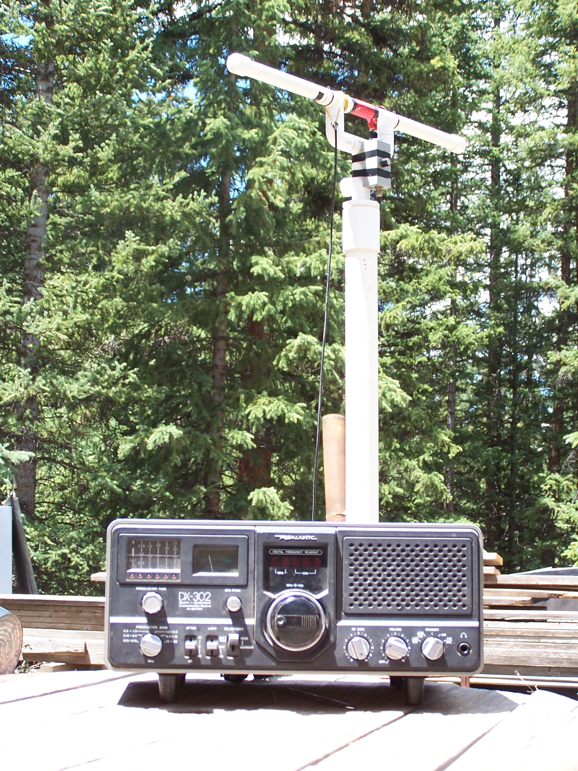
A magnetic loop antenna (shown in the horizontal position) for measuring radio-wave emissions of Tesla coil transmitters. The coil is 170 turns of AWG 22 magnet wire on a 31" x 1" 800 µ ferrite rod (mix 43) for 7.47 mH, connected to a 384 pF variable capacitor. A 561 pF ceramic disk capacitor is connected to the banana jack/screw terminals on the box. The total capacitance needed to tune down to 60 kHz is 850 pF. Coupling to the antenna is with four full turns of ordinary stranded hookup wire, forming the secondary of a receiving transformer. The attached VLF receiver is tuned to 60 kHz WWVB Fort Collins, Colorado for the purpose of antenna performance evaluation. |
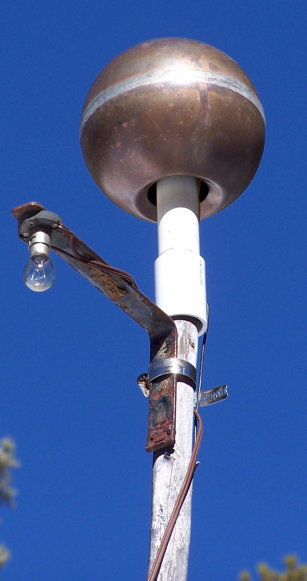
| An elevated terminal capacitance used in conjunction with an analog voltmeter for peaking Tesla coil transmitters, and a frequency counter for transmission frequency measurement. |
| July 27, 2002 A grounded Tesla coil RF energy transmitter and Tesla coil RF energy receiving transformer pair was used to obtain signal-strength measurements at various distances of separation. The input to the transmitter's primary was .750 - 1 amps at 23.83 volts for an approximate transmitter power output of approximately 18 to 24 watts--no more than 25 watts. Initial tune-up was accomplished using an analogue volt meter and also a small incandescent Xmas tree lamp, either connected directly to the receiver's secondary coil terminals. The lamp could be made to glow dimly at 10.7 meters (35'). A small permanent magnet dc electric motor with a full bridge diode rectifier could be made to run at approximately half that distance. At distances slightly greater than 11 meters a Fluke True RMS Multimeter was used as an E-field probe to sense the pulsating electric field associated with the vertical conductor that connects the helical resonator to the elevated terminal. A wire lead was connected to the V input of the meter and brought into close proximity with vertical conductor. The meter's COM input was connected to a point in common with the bottom lead of the receiver's helical resonator at the end of a 58' ground insulated wire lying on the ground and connected to a 20-foot steel water well casing. With the receiving transformer located at a distance of about 60 m (200') from the transmitter, a 204 - 230 mVAC reading was observed on meter (Al foil off of roll = 34.9 cm (13.75")). A low frequency radio communications receiver with a 20' wire antenna plus ground was used to characterize the Tesla coil transmitter's radio-wave output. At the same distance of about 60 m. (200') from the Tesla coil transmitter no associated radio wave energy could be observed. In the future a tuned magnetic loop antenna will be used to characterize Tesla coil transmitter radio-wave output. The Tesla coil RF energy receiving transformer was then moved to a position roughly 152 m (500') from the transmitter. The resonator's ground connection was made with a 16.8 m (55') insulated ground wire running across the ground to a 12.2 m (40') steel water well casing. The V lead of the AC volt meter arrangement described above was once again brought into close proximity with the above-described vertical conductor with ambiguous results. The multimeter was then replaced with a low frequency radio communications receiver. The wire lead (VAC) running to near the resonator-elevated terminal conductor was connected to one of the communications receiver's 300-ohm antenna terminals. The ground lead was connected to the other 300 ohm antenna terminal (with the ground jumper in place). With this arrangement an S7 field-strength reading was observed on the receiver's field strength meter (Al foil off of roll = 24.8 cm (9.75")). It is noted that the transmitter was almost certainly out of tune due to instability of the pulse generator. With the Tesla coil energy receiving transformer located at a distance of approximately 1 km (.621 mi.) from the transmitter and the transmitter precisely in tune, an S5 field-strength or 14 microvolts reading was observed on the receiver's field strength meter (Al foil off of roll = 43.8 cm (17.25')). This works out to a minimum received power of 3.92E-12 watts and a throughput efficiency of about 1.63E-13%. In addition to the field strength reading, a pronounced suppression of the background thermal RF noise was noticed. Once again, there were no measurable radio waves at 60 meters from the Tesla coil transmitter. Preliminary Conclusions Given that a connection was established between the Tesla coil RF transmitter and the Tesla coil RF receiver, and that energy was transmitted and subsequently collected at the receiving location that was in excess of 1/3-wavelength from the transmitter, while under the same Tesla-coil transmitter conditions a radio wave receiver at a much closer distance was unable to detect the transmitted energy, then tenuous empirical evidence exists that the transfer of energy is not by means of "radio waves." By the way, the ongoing investigations, partly described above, have demonstrated that Tesla was right in regards to another disputed physical principle, that is the capacity of an insulated spherical conductor in space increases as a function of elevation above the earth's surface. Transmitter Construction Details -- The transmitter's resonator has a 7:1 aspect ratio. With the door-knob topload it resonates at about 185 kHz. With the 58.4 cm (23") diameter aluminum disk elevated terminal in place the resonant frequency is measured at 107.83 kHz . Frequency counter is a Fluke True RMS Multimeter. Excitatation circuit Interdesign square-wave pulse generator H11L3GE optoisolator IRF640 power MOSFET and associated circuitry 24 volt DC power supply (2 12 volt lead-acid car batteries) Primary coil coil form (spool): upper portion of a 5-gallon plastic pail Diameter: 29.2 cm (11.5") Length: 5.4 cm (2.125") Wire size: AWG #14, type MTW THWN THHN AWM 600 volt Turns: 18 Winding length: 5.4 cm (2.125") Secondary coil (helical resonator) Coil form: 3.18 mm (1/8") + cardboard cylinder with 2.38 mm (3/32") acrylic ends, with a few light coats of polyurethane finish (Grace Ice & Water Shield cylinder) Diameter: 13.5 (5.3125") Length: 96.5 cm (38") Wire size: AWG #24 magnet wire (Nyleze) Turns: 1740 Winding length: 95.3 cm (37.5") Inductance: 54.6 mH Resistance: 72.7 ohms Height of bottom turn above ground: 45.7 cm (18") Elevated terminal Aluminum disk Diameter: 58.4 cm (23") Thickness: 3.18 mm (0.125") Height above top turn: 2.48 m (97.5") Height above ground: 3.89 m (153") Ground terminal Two copper bonded steel rods, 1.71 cm x 2.44 m (5/8" x 8'), with 20.3 cm (8") spacing, driven into the water table at a depth of approximately 1.22 m (4') below grade Connecting wire: 4.27 m (14') AWG #10 (stranded) + 6.55 m (21.5') AWG #16 cord Receiver Construction Details -- A Tesla coil RF energy receiving transformer with widely-adjustable variable elevated terminal. Primary Coil form: Single layer of craft paper with 2.38 mm (3/32") acrylic ends, coated with polyurethane finish Form diameter: 27.9 cm (11") Form length: 45.7 cm(18") Primary wire size: AWG #22 magnet wire (Nyleze) Turns: 630 (approx.) Winding length: 44.5 cm (17.5") Inductance: 57.5 mH Resistance: 28.5 ohms Height of bottom turn above ground: 41.9 cm (16.5") Secondary Wire size: AWG #18 cord (close wound) Secondary turns: 18 (ends left open, i.e., diminutive lamp load disconnected when E-field probe 'detector' is used) Winding length: 1.68", first turn starts 0.875" above lowest primary turn Elevated terminal ('curtain cap') Aluminum foil rolled on to a 7/8" wooden dowel Foil width: 18" Foil length: adjustable from 1.5" to 60" Maximum height above top turn: 1.88 m (74") Ground terminals 6.1 m (20') steel water well casing; 12.2 m (40') steel water well casing; municipal fire hydrant Connecting wire: 16.8 m (55') insulated AWG #14 cord. |