WARDENCLYFFE AND THE WORLD SYSTEM : The history and design of
Tesla’s
wireless telecommunications facility on Eastern Long
Island
“The tower was destroyed two years ago but my projects
are being developed and another one, improved in some features, will be
constructed. . . . My project was retarded by laws of nature. The world was not prepared for it. It was too far ahead of time, but the same
laws will prevail in the end and make it a triumphal success.” — Tesla,
1919
I. INTRODUCTION
AC
power, fluorescent lighting, wireless telecommunications and digital computing,
these are all familiar and vital components of life as we know it in the twenty-first
century and all were contributions of the prolific inventor Tesla. In spite of their exceptional significance,
there are additional inventions that this remarkable man left to the world with
the capacity to be of an equivalent or perhaps even greater value to
society. Much of Tesla's legacy,
that which can be read about, built and used, is in the form of these
inventions—much but not all.
Near
the North Shore Long Island community of Shoreham, New York there exists a
sturdy 94 by 94 foot red brick structure that is another, no less significant
reminder of this great man's work. Its
importance lays not so much in the technology that it represents or in the
engineering clues that remain buried there.
It is in the fact that the Wardenclyffe Power Plant / Office Building,
designed by the well renowned architect Stanford White, is the last of Dr.
Tesla's own work places to remain standing anywhere in the world. The saga of the building's history, from its
construction in 1902 alongside a 187-foot companion tower to house the various
components of a prototype world broadcasting and telecommunications facility to
later less glamorous uses, is a story yet to be fully told. And, there is history in the making as well. For a movement is underway which, if
successful, will result in the establishment of the Tesla Science Center at
Wardenclyffe—a permanent monument to this great creative genius and his work.
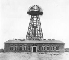
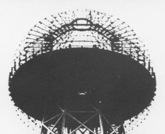
Figure 1. The Wardenclyffe
facility for worldwide broadcasting and wireless telecommunications.
II. BACKGROUND
Just
to the east of Manhattan, Tesla's principle place of residence from 1884
until his death in 1943, is another somewhat larger body of land known as Long
Island. Extending about 115 miles along
the Atlantic shoreline of the United States, this 12 mile wide island is
bounded by Long Island Sound to the north, and the East River, New York Bay and
the Narrows to the west. It was formed
due to the effect of glaciations, with its geography being defined by the
deposition of two glacial moraines and associated outwash plains.
Settlement
of the area started in the late 1600s and continued on through the year 1800,
after being purchased from the indigenous people known as the Montauks. The occupations of the residents were mainly
related to farming, a character that the area retains to this day. A cordwood industry eventually developed as
well, with logs of chestnut, oak and pine being shipped by sailing vessel to
heat homes and fuel brickyard kilns in nearby New York City. Around 1850 the effects of an increasing
demand for fuel along with a chestnut blight combined, resulting in forest
depletion. The introduction of coal as
wood's replacement occurred at the same time.
III.
WARDENCLYFFE-ON-SOUND
About
50 years later, having just returned to New York from a productive scientific
expedition at the edge of the Colorado Rockies, Tesla was anxious to put
a mass of newfound knowledge to work.
His vision was focused on the development of a prototype wireless
communications station and research facility, and he needed a site on which to
build. Long Island was already home to
more than one-and-a-quarter million people when in 1901 he cast his eyes some
60 miles eastward to the north-shore village of Woodville Landing. Only six years before the northern branch of
the Long Island Railroad had opened, reducing travel time to the locality from
a horse-drawn five hours to less than two.
Seeing
an opportunity in land development, a western lawyer and banker by the name of James
S. Warden had purchased 1400 acres in the area and started building an
exclusive summer resort community known as Wardenclyffe-On-Sound.[1] With an opportunity for further development
in mind, Warden offered Tesla a 200-acre section of this parcel lying directly
to the south of the newly laid track. It was anticipated that implementation of
Tesla's system would eventually lead to the establishment of a "Radio
City" to house the thousands of employees needed for operation of the
facility. The proximity to Manhattan
and the fairly short travel time between the two, along with the site's
closeness to a railway line must have been attractive features and Tesla
accepted the offer.
The
Wardenclyffe World Wireless facility as envisioned by Tesla was to have been
quite different from radio broadcasting stations, as they presently exist. While there was to be a great similarity in
the apparatus employed, the method in which it was to be utilized would have
been radically different. Conventional
transmitters are designed so as to maximize the amount of electromagnetic
radiation emitted by the antenna structure.
For long-range communications such equipment must process tremendous
amounts of power in order to counteract the loss in field strength (P = 1/R2)
encountered as the signal radiates outward from its point of origin. The transmitter at Wardenclyffe was
configured so as to minimize the radiated power. The energy of Tesla's steam driven Westinghouse 200 kW alternator
was to be channeled instead into an underground structure consisting of iron
pipes driven from a point 120 feet beneath the tower's base.[2] This was to be accomplished by combining an
extremely low frequency signal (ELF) along with the higher frequency current
coursing between the earth and the transmitter's elevated terminal [through the
master oscillator and helical resonator].
The low frequency current in the presence of an enveloping
corona-induced plasma of free charge carriers would have "pumped" the
earth's charge.[3] It is believed the
resulting ground current and its associated wave complex would have allowed the
propagation of wireless transmissions to any distance on the earth's surface
with as little as 5% loss due to electromagnetic radiation.
The
terrestrial transmission line modes so excited would have supported a system
with the following technical capabilities:
1. Establishment of a multi-channel global broadcasting system with programming
including news, music, et cetera;
2. Interconnection of the
world's telephone and telegraph exchanges, and stock tickers;
3. Transmission of written
and printed matter, and data;
4. World wide reproduction
of photographic images;
5. Establishment of a
universal marine navigation and location system, including a means for the
synchronization of precision timepieces;
6. Establishment of secure
wireless communications services. [4]
Additional World System
capabilities and related technologies include,
7. Remote control and propulsion of UAV "atmospheric
satellites" in long duration flight.
8. Wireless transmission of electrical energy for propulsion of
aerial and other vehicles, and industrial purposes.
9. Geophysical exploration [Waite]
10. Weather control,
artificial rain; climate control
11. Macroscopic charged
particle beam projection
12. Electrical projection of
explosive energy
13. Electrotherapeutics
14. Electronic logic gate
and digital computing allow,
a) Software defined radio
b)
Digital world-system broadcasting and terrestrial network backbone
b) Artificial intelligence
15. Interplanetary
Communications providing a stable, high-capacity interplanetary network
backbone supporting high-speed Internet protocols.
IV. THE WARDENCLYFFE POWER
PLANT AND LABORATORY -- History and Design
The design of Tesla's World-System installation can be traced back to 1892 and his preliminary investigations at the 35 South Fifth Avenue lab. In Tesla‘s words, “The first gratifying result was obtained in the spring of the succeeding year, when I reached a tension of about 1,000,000 volts with my conical coil.” Further development took place in his Houston Street lab where he achieved potentials of 4,000,000 volts with a larger flat-spiral coil.
[Insert comments about the observation of different receiving coils selectively responding to the action of the N.Y. oscillator.]
He
made observations related to selective tuning, developing techniques for
spreading the transmitted RF energy in both the frequency and time domains --
spread spectrum transmission.
In
1899 Tesla went to Colorado Springs to learn how the apparatus would be best
constructed and how to control the even higher potentials that would involved
in the operation of a large industrial plant such as was being contemplated. There, using a gigantic form of electrical
oscillator called the magnifying transmitter, he produced what were, at the
time, the greatest point-to-point discharges ever achieved by man. The potentials involved were in the order of
12,000,000 volts. The master oscillation
transformer was 49 1/3-feet in diameter and 6 1/2 feet high. The extra coil was 8 feet across by 8 feet
high. [Antenna currents reached 800 amperes, describe intense luminosity of
tower.]
Upon
the conclusion of his preliminary investigations Tesla wrote
Westinghouse,
I have just returned from Colorado, where I have been carrying on some experiments since a few months past. The success has been even greater than I anticipated, and among other things I have absolutely demonstrated the practicability of the establishment of telegraphic communication to any point on the globe by the help of the machinery I have perfected.
Tesla’s
short-term goal was to build a prototype world-system communications
facility. This was intended as the
first of many wireless plants that would be located near major population
centers around the world. If the
program had moved forward without interruption, the Long Island prototype would
have been followed by additional stations, the first being built somewhere along
the southern coast of England. [5] By
the Summer of 1902 Tesla had shifted his laboratory operations from the Houston
Street Laboratory to the rural Long Island setting, and work began in earnest
on development of the plant. The
building was essentially completed and octagonal wooden tower had taken
form. A 200 kW Westinghouse alternator
was installed to power the system, with four large oil filled transformers as
the high voltage supply. Four
additional steel tanks contained condensers, and another a set of regulating
coils. Designed by Tesla and
Westinghouse engineers, two of these complex units were assembled. One was delivered to Wardenclyffe and the
other was warehoused, presumably for future delivery to the second installation
to be built across the Atlantic.
In
1903 the 187-foot tower framework was topped off with a 68-foot diameter,
55-ton terminal capacitance. A graphic
rendering by artist Frank Paul, shows final appearance of the massive structure
had it been completed.
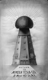
Figure 2
In
order to provide the requisite ground connection Tesla excavated a 120 foot
deep, 10 x 12 foot wood and steel-lined shaft directly below the tower. Using special machines at the bottom of the
shaft, individual sections of steel pipe were pushed piece by piece into the
Long Island subsoil. This provided the
electrical connection that would allow Tesla‘s apparatus, in his words, “to get
a grip of the earth.” [Footnote 1.]
In
July 1903 Tesla began testing the system.
Judging from his letter of November 5 to J.P. Morgan he was not at all
satisfied with its performance.
November 5, 1903,
Dear Mr. Morgan:-
The enclosed bears out my statement made to
you over a year and a half ago. The old
plant has never worked beyond a few hundred miles. Apart of imperfections of the apparatus design there were four
defects, each of which was fatal to success.
It does not seem probable that the new plant will do much better, for
these faults were of a widely different nature and difficult to discover.
As to the remedies, I have protected myself
in applications filed 1900-1902, still in the office.
Yours
faithfully,
N.
Tesla
The
"old plant" appears to be a reference to the Colorado Springs
Experimental Station. A fair estimate
of the ‘imperfections’ can be made through a comparison with the final
Wardenclyffe Plant design. For
starters, the Colorado Springs extra coil had a height-to-diameter ratio of 1:1
(see figure 7 below). The
Wardenclyffe extra coil illustrated in U.S. Patent, No. 1,1191,732,
"Apparatus for Transmitting Electrical Energy," Dec. 1, 1914, shows a
height-to-diameter ratio of 9.1:1.
Second, the elevated capacitance in Colorado consisted of a relatively
small sphere mounted on top of a tall and slender metal mast. In contrast, the Wardenclyffe elevated
capacitance consisted of a large oblate spheroid mounted on top of an
insulating wooden structure. In the
1914 patent the connection from the top of the extra coil to the elevated terminal
is shown as a relatively short, large diameter metal cylinder. [Footnote 2.]
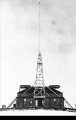

Figure 3. A scale comparison of the Colorado Springs Experimental Station and a Wardenclyffe-type installation.
Another “defect" of the Colorado Springs plant could have been the plan that involved coupling by corona discharge between the extra coil and the conducting hood that Tesla had installed at the lower end of the insulated metal tower (see CSN pp. 197, 334, Phot. X for example).

Figure 4. Colorado
Springs Notes, pp. 197, 334, Phot. X.
Additional
problems may have included the ‘antenna’ feed point (see CSN, pp. 170,
197) and the shallow Colorado ground plate verses the 300-foot long section of
pipe at the bottom of a 120-foot deep shaft [see The Connection to Earth].
In
spite of these and some additional shortcomings, the Colorado apparatus served
as an effective test bed for experimentation with various transmitter
configurations. Six different
arrangements were developed, and are shown in the Colorado Springs Notes
on pages 190 and 191, and also a reproduction of Tesla’s original lab note on
page 200. It seems that Tesla felt the
arrangement illustrated in figures 5 and 6 was the most promising. It shows up with slight variations at a number
of places in the Colorado Springs Notes, most significantly on pages 191, 200,
197 and 170 (see also pages 161, 162, 174, 177 and 184). In the corresponding text on page 191 Tesla
writes, "In Fig. 5. & 6. it is found best to make [the] extra coil 3/4
wave length and the secondary 1/4 for obvious reasons." In the May 29, 1901 note Tesla wrote of the
Wardenclyffe Design, "The length of conductors in the free system
[equivalent to the 3/4 lambda extra coil in figure 5/6 CSN p. 191/200] should
be lambda/4, and the length of the discharging circuit [equivalent to the 1/4
lambda secondary in figure 5/6] should be 3/4 lambda or n/4 lambda [“n” could
be very large reflecting the wavelength of the superimposed ELF excitation.
[?]] eventually, n being an uneven number."
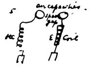
Figure 2. One
of the transmitter configurations illustrated in the Colorado Springs Notes
(figure 5, p. 191/200).
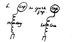
Figure 3. This is the Colorado Spring’s configuration that was incorporated into the initial Wardenclyffe design. [CSN, figure 6, p. 191/200]
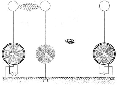
Figure 4.
Another rendering (from an unknown source) of the transmitter
configuration illustrated in figure 6, pp. 191, 200 of the Colorado Springs
Notes. A receiving circuit is
standing out to the right.
The
initial conceptual plan for Wardenclyffe, as illustrated in figure 4, was tied
in with an idea Tesla had that it might be possible to produce displacements in
the earth’s charge without establishing an electrical connection to the upper
atmosphere. This was related to the concept
of energy transmission through one wire without return. The plan called for the installation of two
600-foot tall towers in relatively close proximity to each other. [8]
Alterations
of the initial Wardenclyffe design brought about by the financing issue led to
the arrangement shown in a sketch dated May 29, 1901 (to the left in figure
5). An electrical oscillator or
discharging circuit, consisting of a resonance transformer and an extra coil,
is coupled to the tower structure through an adjustable air gap. The tower cupola is supported on
electrically conducting legs, which, in turn, are attached to a substantial
grounding system. The capacitance of
the cupola relative to the environment, along with the inductance of the tower
legs comprise a separate resonant LC circuit which Tesla designated the “free
system.”
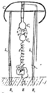
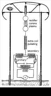
Figure 5. Two design drawings, with variations, of the initial Wardenclyffe transmitter. Tesla calculated the legs would have to be at least 600 feet in length. Notice the alternator-driven discharge circuit and the adjacent free oscillatory system.
The right-hand diagram of figure 5 includes a low-frequency alternator and high-voltage power supply transformer connected to a disruptive-discharge type oscillator. The circuit incorporates a dual capacitor-inductor [LC] arrangement in the oscillatory transformer primary tank circuit along with dual secondary windings. Independent tuning the two sides of the circuit to different frequencies (n/4 lambda, n being an uneven number) would result in the development of a higher order wave complex above the resonant frequency of the extra coil. [“The transmitter was to emit a wave-complex of special characteristics. . . .” My Inventions]
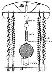
Figure 6. Modified Wardenclyffe transmitter design.
In
figure 6 the straight conducting legs have been modified to a spiral form. An obvious advantage would be a reduction in
the structure’s overall height above ground level. Also notice that the number of turns varies from leg to leg. This would also result in the development of
a higher order wave complex by the transmitter—a form of frequency-division
multiplexing.
While
it’s possible the dual-tower transmitter design might be made to work properly,
it is clear from his experiments with the 1899 through 1901 configuration
culminating with the dismal performance displayed during the July 1903
operational tests that he experienced extreme difficulties with its
single-tower implementation.
Getting
back to the "remedies" in the letter to Morgan, protected in
applications filed between 1900 and 1902, and "still in the office,"
the only patented invention meeting these criteria is APPARATUS FOR TRANSMITTING
ELECTRICAL ENERGY, No. 1,119,732, issued Dec. 1, 1914. Comparing the two basic circuits the most
obvious difference is the elimination of the stand-alone extra coil or free
oscillating system and the plasma coupler [C/S #6]. The entire transmitter is now comprised solely of the discharging
circuit—an oscillatory transformer with an extra coil connected directly to the
elevated terminal.
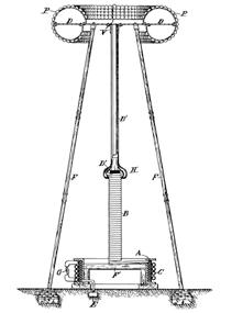
Figure
7. The revised 1902 transmitter design
constituted a departure from the earlier dual tower transmitter originally
planned for the Wardenclyffe facility.
[APPARATUS FOR
TRANSMITTING ELECTRICAL ENERGY, No. 1,119,732, Dr. Tesla Complete Patents. pp. 435-438.]
The
considerable distance (about 350 feet) between the high-voltage power supply
transformers and the tower-side components, including, at the very least, a
helical resonator, could have been a problem on Long Island. Two other seemingly applicable patents filed
for within the specified time period and patented in 1900 are “Means for
Increasing the Intensity of Electrical Oscillations,” No. 787,412 and “Method
of Insulating Electrical Conductors,” No. 655,838, reissued as No. 11,865. Both of these inventions might have been
useful for improving the Wardenclyffe plant's performance; the first for the
magnifying transmitter itself, the second for improving high-voltage power
transmission between the lab building and the tower structure.
In
any case, it can be seen that some major modifications were made to the
design. He later said,
I used the antenna.
I used it right along up to 1907.
I made my measurements and experiments, and I transmitted for the
purpose of tests, energy and all that, but it never went further than is shown
in the picture. [Tesla On
His Work With Alternating Currents and Their Application to Wireless
Telegraphy, Telephony, and Transmission of Power, Leland Anderson, 21st Century Books, p. 154.]
An
unanswered question is the purpose of what appears to be a flat-spiral coil
suspended within the large elevated terminal [the cupola]. In Colorado Springs Tesla specified a coil
to be used in conjunction with a resonator when no ball termination was
present. The additional inductance
served to lower the resonant frequency of the vibrating system back to the
resonant frequency with the ball present.
It is conceivable this technique was adapted to achieve an overall lower
frequency by using both the additional coil and the terminal
capacitance. [See CSN, p. 203
for illustration of the additional coil, form #5, “coil used in series
with extra coil when ball was not employed.”]
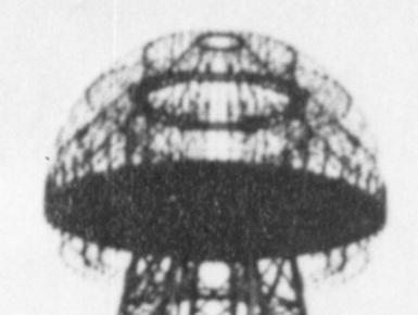
Figures 8a & 8b.
Two views of the Wardenclyffe tower cupola.
FOOTNOTES:
[1] In 1916 Tesla described
the underground portion of the tower this way,
In this system that I have invented it is necessary
for the machine to get a grip of the earth, otherwise it cannot shake the
earth. It has to have a grip on the
earth so that the whole of this globe can quiver, and to do that it is
necessary to carry out a very expensive construction. I had in fact invented special machines. . . . There was a big
shaft about ten by twelve feet goes down about one hundred and twenty feet and
this was first covered with timber and the inside with steel and in the center
of this there was a winding stairs going down and in the center of the
stairs there was a big shaft again through which the current was to pass . . .
And then the real expensive work was to connect that central part with the
earth, and there I had special machines rigged up which would push the iron
pipe, one length after another, and I pushed these iron pipes, I think sixteen
of them, three hundred feet, and then the current through these pipes takes
hold of the earth. Now that was a very
expensive part of the work, but it does not show on the tower, but it belongs
to the tower. [Ref. #2, p. 203]
[2] Two other seemingly applicable patents filed for within the specified time period and patented in 1900 are “Means for Increasing the Intensity of Electrical Oscillations,” No. 787,412 and “Method of Insulating Electrical Conductors,” No. 655,838, reissued as No. 11,865. Both of these inventions might have been useful for improving the Wardenclyffe plant's performance; the first for the magnifying transmitter itself, the second for improving high-voltage power transmission between the lab building and the tower structure.
REFERENCES:
[1]
History of Shoreham, Mary Lou Abata, 1979.
[2]
Tesla On His Work With Alternating Currents and Their Application to Wireless
Telegraphy, Telephony and Transmission of Power, L.I. Anderson, Sun Publishing,
Denver 1992.
[3]
"Spherical Transmission Lines and Global Propagation," K.L. Corum and
J.F. Corum, Proceedings of the 1996 International Tesla Symposium, Colorado
Springs, Colorado.
[4]
“My Inventions,” Tesla, Electrical Experimenter, 1919. . . .
[5]
Vojin Popovic, "Tesla the Founder of Radiocommunications," Tesla--Life and Work of a Genius, Yugoslav Society for the Promotion of
Scientific Knowledge, Belgrade, 1976.
[6]
"Wardenclyffe, Forfeited Dream," Leland I. Anderson, Long Island
Forum, Aug., Sept., 1968.
[7]
Tesla On His Work With Alternating Currents and Their Application to
Wuireless Telegraphy, Telephony and Transmission of Power, Leland I.
Anderson, editor, Twenty First Century Books, 2002.
[8]
Anderson, Leland I., Rare Notes From Tesla On Wardenclyffe, Electric Spacecraft
Journal, Apr./May/June Issue 26, Sept. 14, 1998.
[ ] Prodigal Genius — The Life of Tesla, John J. O'Neill, Ives Washburn, Inc., 1944.
[ ] Anderson, Leland I., “The Silent Tower,” The
Old Timer’s Bulletin, (Antique Wireless Association, Inc.) Autumn (Sept.),
1968.
[ ] Tesla--Colorado Springs Notes,
1899-1900, Tesla Museum, 1987.
[ ] Tesla — Man Out Of Time, Margaret Cheney,
Prentice Hall, 1981.
[ ] "Sale of Nicola Tesla Property
Recalls Stories of Aged Inventor," Brooklyn Eagle, April 24, 1939.
[ ] "Radio Pioneer at Shoreham,"
Thomas R. Bales, Patchogue Advance, Sept. 13, 1951.
[ ] "RI/FS Work Plan," Groundwater
Technology, Sept. 30, 1993.
[ ] "In Recognition," Brookhaven
Bulletin, July 12, 1976.
Miscellaneous
notes:
Tesla's
method of wireless transmission was covered by the following U.S. Patents:
No.
613,809, "Method and Apparatus for Controlling Mechanism of Moving Vessel
or Vehicles," Nov. 8, 1898.
No.
645,576, "System of Transmission of Electrical Energy," Mar. 20,
1900.
Nos.
685,953, 685,954, 685,955, and 685,956, Nov. 5, 1901, on utilizing effects
transmitted through natural media.
The
AND logic-gate patents,
No.
723,188, "Method of Signaling," Mar. 17, 1903.
No.
725,605, "System of Signaling," Apr. 14, 1903.
No.
787,412, "Art of Transmitting Electrical Energy Through the Natural
Mediums," Apr. 18, 1905.
No.
1,1191,732, "Apparatus for Transmitting Electrical Energy," Dec. 1,
1914.
Some
of Tesla's inventions have long been accepted as part of daily life, for
example AC power, broadcasting and, more recently, high frequency
lighting. And, Tesla turbo-machinery
are just now beginning to see some use, especially in the industrial
arena. This is not so much the case
with Tesla's more advanced concepts.
The proposed "World System" is a prime example. Here is a major invention in which Tesla
held total confidence regarding its performance characteristics were it to
become fully operational. Was Tesla
entirely correct? If so, what would be
the ramifications associated with the system's full-scale implementation? Would responsible operation have been
possible or even probable at the beginning of the last century? Even now, could the system gain acceptance
from society, in spite of what might be perceived as less-than-desirable
characteristics, i.e., its potential as a weapon of mass destruction.
It
has been said the prototype plant was intended as the first installation in a
global power distribution system.
Actually, it was intended to serve as the western component of a
trans-Atlantic wireless telecommunications link.
It
is possible the modified dual-tower design was experimented with at
Wardenclyffe, some time between June 1901 and Nov. 1903, as progress with the
tower's construction allowed. In any
case, the letter suggests the 1901 scheme was fatally flawed.
My Inventions, Chapter 5
“. . . A plant was built on Long Island with a tower 187 feet high, having a spherical terminal about 68 feet in diameter. These dimensions were adequate for the transmission of virtually any amount of energy. Originally, only from 200 to 300 K.W. were provided, but I intended to employ later several thousand horsepower. The transmitter was to emit a wave-complex of special characteristics and I had devised a unique method of telephonic control of any amount of energy.
“Morgan, who had invested in a project to capitalize on multichannel wireless message transmissions across the Atlantic, was not the least bit interested in industrial power transmission—which Tesla viewed as the ultimate goal.”
“Local residents were aroused at night by
startling lightning-like flashes, but no one knew exactly what the activities
were at the plant because the whole operation was shrouded in secrecy.”
“Large multi-strand cables connected the
shaft termination to the periphery of the sphere.”
Additional
figures:
35
South 5th Avenue
Houston
Street