Comparative Study of the Hertz, Marconi and Tesla
Low-Frequency Wireless Systems
Four
Launching Structures Considered
Comparing the Four Launching Structures
Comparison of Marconi- and Tesla-type Launching
Structures
Electromagnetic
Radiation vs. Electrical Conduction
The
Norton and Zenneck Surface Waves
Antenna Theory
and Impedance Matching
Capacity of an Elevated Sphere
Tesla’s
Priority in the Invention of Radio
Investigation of Tesla-Type Wireless Propagation
[mathematical modeling and physical validation]
Four Launching Structures
Considered
Consider four basic forms of wireless telecommunications
antenna or launching structure, each excited by a radio-frequency power
supply.
The first is the Hertz antenna, a vertical 1/2-wave dipole
antenna, center fed, positioned 1/2 wavelength above the ground. Clearly this is not a very practical
configuration at low frequencies.
Nevertheless, it would be possible to improvise a temporary low
frequency vertical dipole by suspending a ¼-wavelength section of wire beneath
a large helium balloon. The transmitter
and battery, mounted in a lightweight box, is attached at the lower end of this
wire. A second ¼-wavelength section of
wire is connected to the transmitter.
Finally the entire assembly is allowed to rise into the air, tethered by
a long nylon line. Insulators are inserted
at the antenna ends for good measure.
The transmitter itself would be wirelessly remote controlled, and could
be configured as a cross-band repeater.
Next is the Marconi antenna, a vertical 1/4-wave ground-plane
monopole antenna element above a conducting surface, at or slightly above
ground level. A vertical conductor with no loading coil and no capacitive
top loading is assumed. It is fed at its base by an RF power supply plus
an appropriate matching section, with the opposing terminal connected to an
elevated ‘counterpoise’ constructed on insulating supports. As an alternative to the counterpoise, a
connection is made directly to the earth’s surface. This shallow ground connection is constructed so as to introduce
the least possible resistance.
Restrictions are imposed by the depth and surface area of the buried
conductors, and the local ground conductivity.
The third and forth are the type-one and type-two Tesla
launching structures.
The type-one structure is a single a vertical high
aspect-ratio 1/4-wave helical resonator with large capacitive top loading and
small overall height compared to the electrical 1/4 wavelength. The
1/4-wave resonator is base fed by a low impedance RF power supply, with the
opposing terminal grounded. The ground connection is constructed in such
a way as to introduce the least possible resistance to ground. In modeling this structure, it is necessary
that a complementary receiving structure of identical physical dimensions to
that of the transmitting element be included in the circuit. The latter may be either an active or
passive receiving element. This system
is used when employing the atmospheric conduction method.
The type-two structure consists of two type-one structures,
identified as element A and element B, of identical physical dimensions, in
close proximity to each other. Element
B may be either an active or a passive transmitting element. This system is used when employing the earth
resonance method. Note that a distant
receiving element is not necessary when modeling the type-two transmitting
circuit.
Comparing the Four Launching Structures
The Hertz
antenna, also known as the 1/2-wave dipole antenna, is considered to be a
physical embodiment of an electric dipole in free space. In terms of efficiency as a radiator, it
approaches an ideal source of electromagnetic radiation emitted in the form of space
waves. These space waves can reach the receiver either by ground-wave
propagation or by reflection from the ionosphere, known as sky-wave
propagation. [Sky waves are not broadly addressed in this paper.]

The
electric field that develops when an AC voltage is applied to the terminals of
a dipole antenna.
The ground-wave
component is the portion of the radiated space wave that propagates close to
the earth's surface. It has both
direct-wave and ground-reflected components, and under certain conditions a
tropospheric ducting component. The
direct-wave is limited only by the distance to the horizon from the transmitter
plus a small distance added by atmospheric diffraction around the curvature of
the earth. The ground-reflected portion
of the radiated wave reaches the receiving antenna after being reflected from the
earth's surface. A portion of the
ground-wave energy radiated by the antenna may also be guided by the earth's
surface as a ground-hugging surface wave.
The
induced ground-hugging surface-wave component of the ground wave is known as
the Norton surface wave. It is the result of electrical currents induced in the ground
by refraction of a portion of the reflected-wave component at the
earth-atmosphere interface. Upon
reflection from the Earth's surface the ground-reflected wave undergoes a
180deg phase reversal. When both transmitting and receiving antennas are
on, or close to, the ground and the distance between them approaches the
above-described limit, the direct and reflected components tend to cancel each
other out, and the resulting field intensity is principally that of the surface
wave. Because the ground absorbs part of its energy, the electrical
intensity of the surface wave is attenuated at a much greater rate than
inversely as the distance. It is the conductivity of the underlying terrain
that determines the attenuation of the surface-wave field intensity as a
function of distance. The ground currents of a vertically polarized
surface wave do not short-circuit a given electric field but rather serve to
restore part of the used energy to the following field. The better the
conducting surface layer, the more energy returned and the less energy
absorbed. [Antennas and Radio Propagation, TM 11-666, Dept. of the Army,
Feb. 1953, pp. 17-23.] Prevailing radio
wave propagation theory teaches that the surface-wave component is wholly the
result of electrical currents induced in the ground by refraction of a portion
of the reflected-wave component.
The Marconi antenna is a
modified 1/2-wave dipole Hertz antenna, adapted to the real-world conditions
encountered in the construction of low frequency transmitters. These
adaptations are imposed by the wavelength involved and the resulting physical
dimensions required of the antenna. The dipole antenna is modified in
that its lower half, 1/4 wavelength long, exists only as an electromagnetic
mirror image of its upper counterpart. The resulting 1/4-wave vertical
‘monopole’ antenna takes advantage of the fact that the lower half of the
antenna, i.e., the ‘counterpoise,’ acts as a mirror for the radiated
energy. This type of structure is known as a ground plane antenna.
The
so-called ‘counterpoise’ is a radially symmetrical wire structure erected on
insulating supports a short distance above the earth’s surface. One school of thought asserts that the
counterpoise operates solely by virtue of its capacitance to the ground. The counterpoise has been defined as “a
conductor or system of conductors used as a substitute for earth or ground in
an antenna system” [Weik '89].
The
counterpoise, in fact, simply forms part of the radiating antenna. It exhibits a current distribution
comparable to the current distribution on the vertical monopole section. Radiation from the ‘counterpoise’ is
horizontally polarized and, for the most part, self-canceling in the far-field
region. (See “Counterpoises,
Capacity Hats, and A Standard for Comparing Antennas Suspected of Radiation
from the Feedline,” L. B. Cebik, W4RNL, http://www.cebik.com/gp/cp-th.html )
For low
frequency antennas it is common practice to bury the counterpoise a few inches
in the ground, taking advantage of the earth’s conductivity to increase the
physical size of the ground plane. The ground
reflects a large amount of the energy that is radiated downward from the
antenna mounted over it. In the physical construction of the ground plane
it is important to have as high a ground conductivity as possible. The objective is to provide the best
possible reflecting surface for the downward radiated energy from the
antenna. Typically, the ground plane
consists of a number of 1/2 wavelength long bare conductors arranged radially
and connected together, buried a short distance [6-8 inches] beneath the
earth's surface. These conductors act as part of the reflecting surface
as well as making the connection to ground itself.
Not unlike
the Hertz antenna, the Marconi antenna is intended as a source electromagnetic
radiation in the form of space waves. As with the Hertz antenna, the
ground wave component takes both a direct and reflected path from the
transmitter to the receiver, and it may also be guided along the earth's
surface as a ground-hugging Norton surface wave.
A rough
approximation of the e-field lines associated with and near to a grounded
¼-wave monopole antenna located on the earth’s surface. In reality, as the distance from the
radiator increase, the e-field lines close back upon themselves to form
electromagnetic waves in free space.
The above
rendering is a very rough approximation of the e-field lines associated with a
¼-wave ground-plane monopole antenna located on the earth’s surface. The inaccuracy increases rapidly as the
distance from the radiator increases.
The actual radiation pattern is described in terms of antenna radiation
fields. There are three traditional radiation fields in free space
as a result of an antenna radiating power. The near-field region is that
is closest to the transmitting antenna in which the reactive field dominates
over the radiative fields. This region
is shown fairly accurately.
Just beyond this is the Fresnel zone
in which the radiation fields begin to dominate. An accurate representation will show the e-field lines starting to close
back upon themselves to form electromagnetic waves in free space. [Because the earth is neither a perfect
insulator nor a perfect conductor,] some of the closed loops will continue on
for a time extended downward into the earth or lower half space. In the case of an ideal ¼-wave ground-plane
antenna, all of the loops would be in the process of breaking free from the
ground to propagate outward in the form of space waves, both sky waves and
ground waves.
Eventually a distance will be
reached at which all of the loops will have closed back upon themselves. This is the far-field region. Any
interaction between the radiated energy and the earth’s surface in this region
is totally independent of our ideal transmitting antenna. When Tesla spoke of the "Hertz
wave" he was referring, in essence, to far-field electromagnetic
radiation.
The
type-one Tesla ‘antenna’ is also viewed as part of an electric dipole,
consisting of the elevated capacitance, the helical resonator plus connections,
and the earth itself. The aboveground portion is not intended as a source
of electromagnetic radiation; rather, it is designed to minimize the production
of electromagnetic radiation. [The working of the structure's helical
resonator may be associated with a transverse magnetic wave. [Corum &
Corum] and with an interaction with the Earth's magnetic field
[Papadopoulos.] The principle that the ground acts as a mirror, which
reflects electromagnetic energy radiated downward by the antenna mounted over
it, is not applicable. The Tesla launching structure induces ground
currents in the earth, and an associated surface wave. In the air path,
electrical
conduction through plasma and electrostatic induction take place. At the Wardenclyffe facility the ground consists of a 300-foot long vertical pipe driven
downward from the bottom of a 120-foot deep shaft, making the maximum depth of
the ground connection beneath the earth's surface 420 feet. [There
have been differing interpretations of Tesla’s description of the underground
portion of the tower, but this seems to be the best fit. [Personal conversation
with Robert Uth.]

These are
two examples of a type-one transmitter-receiver pair. The lower illustration shows some of the electric field lines
associated with the flow of electrical energy between the transmitter and the
receiver.
In tracing
the flow of energy associated with the type-one transmitter a [phase conjugate]
receiving structure has to be included in the circuit. This may be an identical oscillator
configured as a receiver or passive helical resonator. The energy flowing
between Tesla ground-air transmitter/receiver facilities is in the form of an
electric current flowing through the earth between two ground connections plus
an electric
current flowing in plasma through an air path;
electrostatic induction or so called ‘displacement currents’ can also be
involved.
Conceptually,
the type-two Tesla antenna structure is comprised of a basic type-one system
including the receiving structure.
Rather than being located at a great distance from the main transmitter
oscillator (element A), the receiving structure (element B) is located close to
the oscillator. The minimum spacing
between the two structures might be equivalent to the wavelength of the element
A oscillator frequency divided by 4.
Element B is part of the transmitter circuit, and may be either an
active type-one transmitter oscillator, or a passive top-loaded helical
resonator connected to ground.
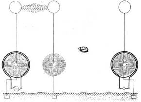
This illustration is an example of a type-two earth-resonance
transmitter. A capacitively coupled
plasma discharge is shown between the transmitter’s two elevated
terminals. The receiving transformer
shown to the right is not necessary for the transmitter to excite earth
resonance.
The type-two
transmitting circuit is used when employing the earth resonance method. It is designed specifically to produce a
local flow of powerful currents in the earth between the two ground terminals. Electrical conduction through plasma takes
place in the air path between the two elevated terminals. Each ground connection is modeled as a
vertical pipe, at least 300 feet long, driven straight down from the bottom of
a 120-foot deep shaft, for a minimum depth below the surface of 420
feet. The energy passing between elements A and B is in the form of an
electric current through the earth between the two ground connections plus an electric current in plasma along
the air
path.
Preliminary
Conclusion
The production of ground currents through the operation of a
dipole in free space differs greatly compared with that of the ground current
associated with the operation of both the type-one [and type-two Tesla
apparatus]. In the first case, the
current is induced by the refraction of space waves emitted from a distant
transmitting antenna. In the second
case an electric current is caused to flow through the earth between two
specific, discreet, well-defined points on its’ surface. In this case the transmitted energy passes
between the transmitter and receiver by a combination of electrical current
flowing through the earth, and electrostatic induction and/or electrical
conduction through plasma with an embedded magnetic field. Unlike the ½-wave dipole antenna, the type-one
transmitter’s launching structure is not intended as a source of
electromagnetic radiation; rather, it is designed to minimize the production of
electromagnetic radiation. The
principle that the ground plane acts as a mirror, which reflects electromagnetic
energy projected downward by a ¼-wave monopole antenna mounted over it, is not
applicable.
In both cases there is a surface wave. The space-wave induced current results in the production of the
Norton surface wave according to the mechanism described above. When employing the Tesla apparatus, the
electrical current flowing through the earth between the two elements induces
the surface wave. In somewhat of a
turnaround, the dissipation of electrical energy in the form of ground-current
induced radio waves is viewed as loss in the Tesla system. Considering the vast difference in their
manner of production it’s fair to ask: is this latter wave the Norton surface
wave or something different?
Sommerfeld
described an electrodynamic wave that is guided along a wire of finite
conductivity and Zenneck expanded upon this description, asserting that the
earth's surface performs in a manner similar to a conducting wire. And, while the Norton Surface Wave is the
result of electrical currents induced in the ground by refraction of a portion
of the reflected-wave component of the ground wave at the earth-atmosphere
interface, we know the surface wave associated with Tesla’s apparatus is the
result of electrical ground currents flowing between two points on the earth’s
surface. Unlike the lossy Norton
surface-wave that is excited by a conventional AM radio transmitter it would
seem that Tesla’s surface wave would not diminish quite as significantly as the
distance between the transmitting (or source) and receiving (or load)
facilities increased. This is to be
investigated.
top
Comparison of the Marconi Monopole and the Tesla Type-1 Launching
Structures
At low frequencies, the
Marconi system involves the excitation of a loading coil connected to an
antenna wire. When everything is
properly tuned, the antenna efficiently emits radio waves. These radio waves travel outward through the
surrounding half space in every possible direction. A small fraction of the energy contained in these waves interacts
with or is captured by the distant receiving antenna and detected and amplified
using a radio wave receiver.
In contrast, the basic
full-scale Tesla system consists of two mutually resonant transmitter/receiver
facilities positioned a great distance from each other. Each facility uses transmitter/receiver
circuitry consisting of, in part, a ground connection, a helical resonator and
elevated terminal capacitance. The
electrical energy produced by the two individual sources is conserved within
and exists throughout the entire resonating system, including the earth
itself. If only a single facility is in
operation, acting as a transmitter in the absence of a receiver, then the
transmitter will idle and no energy will be transmitted other than that which
maintains the electrical vibration of the earth, counteracting the losses that
occur in the form of electromagnetic radiation, radio waves, light and heat.
Not unlike
the dipole Hertz antenna, the Marconi antenna is a source electromagnetic
radiation in the form of space waves. Typically, these waves, that is to
say the ground waves, take a direct or reflected path from the transmitter to
the receiver. They may also be guided by the earth's surface as a
ground-hugging Norton surface wave. The direct-wave component of the
ground wave is limited only by the distance to the horizon from the transmitter
plus a small distance added by atmospheric diffraction around the curvature of
the earth. The ground-reflected component is the portion of the radiated
wave that reaches the receiving antenna after being reflected from the Earth's
surface. Prevailing wave propagation theory teaches that the surface-wave
component is wholly the result of electrical currents induced in the ground by
refraction of a portion of the reflected-wave component.
Upon
reflection from the Earth's surface the reflected wave undergoes a 180 degree
phase reversal. When both transmitting and receiving antennas are on, or
close to, the ground, and the distance between them approaches the
above-described limit, the direct and reflected components tend to cancel out,
and the resulting field intensity is principally that of the surface
wave. Because a part of its energy is absorbed by the ground, the
electrical intensity of the surface wave is attenuated at a much greater rate
than inversely as the distance. It is the conductivity of the underlying
terrain that determines the attenuation of the surface-wave field intensity as
a function of distance. The ground currents of a vertically polarized
surface wave do not short-circuit a given electric field but rather serve to
restore part of the used energy to the following field. The better the
conducting surface, the more energy returned and the less energy
absorbed. [Antennas and Radio Propagation, TM 11-666, Dept. of the
Army, Feb. 1953, pp. 17-23.]
Of course
the Tesla antenna is also part of an electric dipole, consisting of the
elevated capacitance, the helical resonator plus connections, and the Earth
itself. As already discussed, the above-ground portion of the structure
is not intended as a source of electromagnetic radiation, rather, it is
designed, in part, to minimize the production of electromagnetic radiation.
The principle that the ground acts as a mirror that reflects the
electromagnetic energy radiated downward by the antenna mounted over it is not
applicable. The Tesla launching structure induces ground currents in the
earth, and an associated surface wave, which propagate the transmitted
energy. This wave may be similar to the
Zenneck surface wave.
At the Wardenclyffe facility the ground consisted of a 300-foot long
vertical pipe driven downward from the bottom of a 120-foot deep shaft, placing
the maximum depth of the ground connection at 420 feet beneath the earth's
surface. The elevated high voltage terminals of the transmitting and
receiving stations are used to establish an interconnecting conducting path
through the rarified upper level atmosphere.
The system Tesla described differs in many respects from the
one implemented by Marconi. There are
also distinct similarities.
Similarities:
In both cases the launching structure is associated with an
electric dipole.
Both involve excitation of the dipole by an appropriate
radio frequency power supply.
Both involve a ground connection and an electrically
conducting aerial structure.
Differences:
Above ground launching structure geometry.
Hertz
antenna, physically extended ½ wavelength from end to end; current and voltage
are in phase.
Marconi antenna consists of a vertical conductor
extending ¼ wavelength above the earth's surface [no loading coil and no
capacitive top loading] and a counterpoise; current and voltage are in phase; common inductive and
capacitive aerial elements.
Tesla
antenna consists of a ¼ wavelength helical resonator with capacitive top
loading – an elevated terminal of large surface area; inductive and capacitive
and inductive elements are physically
separated in space; entire structure a small fraction of ¼ wavelength in
overall height. [What is the phase
relationship between current and
voltage on the structure?]
Power in antenna circuit modeled as parallel LC circuit
Hertz: alternately applied to opposing linear conductors; little reflected power due to high radiation resistance; voltage and current in phase resulting in development of production of E and H fields in phase shifting to quadrature phase relationship.
Marconi: alternately applied to aerial conductor and counterpoise; little reflected power due to high radiation resistance; voltage and current in phase resulting in the development of E and H fields in phase, shifting to quadrature phase relationship.
Tesla: alternately applied to top loaded resonator and ground; high reflected power due to low radiation resistance; do voltage and current exist in quadrature phase relationship on structure?.
I mean this: If you pass a current into a
circuit with large self-induction, and no radiation takes place, and you have a
low resistance, there is no possibility of this energy getting out into space;
therefore, the impressed impulses accumulate. [NTAC, pp.74-75]
Power supply waveform
Hertz/Marconi system: perfectly
sinusoidal AC at oscillator frequency
Tesla
system: dc pulse or square wave at oscillator frequency plus low frequency
impulses of great intensity and short duration.
I reduced the number of poles, I think, in
1901. But then I reduced it for the
purpose of generating currents of higher frequency. If I had a great number of poles, I could not realize my idea,
because these poles would come in quick succession and not produce a rate of
change comparable to the rate of change which is obtainable by the discharge of
a condenser owing to a sudden break of the dielectric. That is to say, a blow. It has to be a blow, you see. I had to place my poles comparatively far
apart, then run them at excessive speed and generate comparatively few
impulses, but each of those impulses are of such tremendous intensity that the
dynamo is practically short-circuited.
That gave me a blow which replaced the arc. . . . [NTAC,
p. 15]
Potential on structure
Marconi antenna, [say] 20 thousand
volts
Tesla antenna, 10-100 million
volts
Grounding system
Marconi antenna: ground consists of multiple [say 90 at four degree spacing] electrical conductors arranged radially and interconnected, 1/2 wavelength long, buried a short distance [6-8 inches] beneath the earth's surface. Alternatively, the ground portion can consist of a wire structure erected a short distance above the ground, and insulated from the Earth. Good ground conductivity is needed to reflect downward radiation. A good ground connection is only necessary to connect to the ‘mirror.’
“One common practice is to mount one half of a dipole vertically on a conducting surface (ground plane). This reduces the size of the aperture by 50%, resulting in a 3 dB loss. As we have seen, a dipole has 2.15 dB gain over an isotropic source; if a 1/4 wavelength antenna on a ground plane has 3 dB loss as compared to a dipole, that means that the "1/4 wave" antenna has 0.85 dB loss as compared to an isotropic source. Some antenna manufacturers express the gain of their products as "gain over a 1/4 wave". An antenna advertized as having 3 dB gain over a 1/4 wave is the same as as an antenna having 2.15 dBi gain or 0 dBd gain. It's the same antenna - the bigger numbers are just that - bigger numbers!
“A somewhat less common practice is to mount
a vertical dipole directly on the ground. This practice is fraught with
problems. A portion of the aperture is beneath the ground. This induces large
currents into the ground surrounding the antenna. With the high (and
uncontrollable) ground resistance, these currents result in substantial voltage
drops. The power lost to heating the ground does nothing more than make the
worms uncomfortable. These losses can be reduced to acceptable levels by
installing an extensive ground system. The severe aperture interference also
causes the antenna to exhibit a high angle of radiation. It would be easier
(and cheaper) to elevate the antenna far enough so that the aperture does not
touch the ground.” [http://k9erg.tripod.com/theory.htm]
Tesla antenna: ground consists of a deeply buried conductor. At the Wardenclyffe facility the ground consisted of a 300-foot long vertical pipe driven downward from the bottom of a 120-foot deep shaft. [NTAC p. 203]
Operating frequency
Marconi / Hertz system: 8 kHz –
100 gHz
Tesla system: fundamental Earth resonant frequency, say 7.5 Hz + 975 Hz to 30 kHz + higher harmonics extending up to 100 gHz
Excitation of propagating medium
Marconi
antenna / half-wave dipole, the electric field energy and the magnetic field
energy are introduced into the field medium in time-phase with each other. The excitation of the medium by the antenna
develops an in phase propagation mode shifting to a quadrature phase
propagation mode, this taking place over the initial range of transmission;
Fresnel zone, also called the radiating near field. The launching
structure provides a good initial impedance match with free space resulting in
the efficient production of electromagnetic waves.
Tesla
antennas, electric current in lower half-space; TM surface wave, spiraling
electrostatic and magnetic flux lines in dielectric portion of upper
half-space; electric current and magneto-hydrodynamic waves in ionized portion
of upper half-space. The launching structure is
specifically designed to have a poor impedance match with free space. Its
configuration inhibits the launching of electromagnetic space waves.
Provided with sufficient input power, a large magnifying transmitter is capable
of ionizing and breaking down the denser insulating portions of the earth's
atmosphere around and above it, rendering this medium electrically conducting.
Energy flow
Marconi system involves the
passage of energy in a single direction.
Tesla system permits two-way
passage of electromagnetic energy.
Additional
Hertz/Marconi: Discrete
transmitters and receivers
Tesla: Conjugate transmitter/receiver installations; Floating grounds for energy storage; transmitted wave is in higher order group symmetry form; 3-wave, 4-wave . . . n-wave mixing; permits parametric pumping without auxiliary power input source.
Propagation mode
Hertz/Marconi: Electromagnetic radiation (Space wave), ground wave (direct, reflected, and Norton surface wave) and reflected sky wave.
Tesla: electrical conduction, earth currents and associated surface wave; air path by conduction in plasma and electrostatic induction. In Tesla’s words,
“The earth is 4,000 miles radius. Around this
conducting earth is an atmosphere. The earth is a conductor; the
atmosphere above is a conductor, only there is a little stratum between the
conducting atmosphere and the conducting earth which is insulating. . . .
Now, you realize right away that if you set up differences of potential at one
point, say, you will create in the media corresponding fluctuations of
potential. But, since the distance from the earth's surface to the
conducting atmosphere is minute, as compared with the distance of the receiver
at 4,000 miles, say, you can readily see that the energy cannot travel along
this curve and get there, but will be immediately transformed into conduction
currents, and these currents will travel like currents over a wire with a
return. The energy will be recovered in the circuit, not by a beam
that passes along this curve and is reflected and absorbed, . . . but it will
travel by conduction and will be recovered in this way.”
Tesla asserted the propagation mode
was dependent upon transmitter design and operating frequency.
You see, the apparatus which I have devised was an apparatus enabling one to produce tremendous differences of potential and currents in an antenna circuit. These requirements must be fulfilled, whether you transmit by currents of conduction, or whether you transmit by electromagnetic waves. You want high potential currents, you want a great amount of vibratory energy; but you can graduate this vibratory energy. By proper design and choice of wavelengths, you can arrange it so that you get, for instance, 5 percent in these electromagnetic waves and 95 percent in the current that goes through the earth. That is what I am doing. Or you can get, as these radio men, 95 percent in the energy of electromagnetic waves and only 5 percent in the energy of the [earth] current. . . . The apparatus is suitable for one or the other method. I am not producing radiation with my system; I am suppressing electromagnetic waves. . . . In my system, you should free yourself of the idea that there is radiation, that the energy is radiated. It is not radiated; it is conserved. . . . [NTAC, p. 132]
In radio, the transmitter and
receiver function independently of each other.
The transmitting element, in the case of the Marconi antenna, consists
of a vertical single-linear-wire conductor having both inductance and capacity,
and a corresponding ground-plane image.
The receiving element is also a single linear wire electrical conductor
having both inductance and capacity. The transmitter emits an electromagnetic
wave, which separates itself from the antenna and radiates outward. The receiving antenna intercepts a portion
of this wave, the energy of which is detected and utilized. The net energy flow is in one direction,
away from the antenna. The energy moves
away from transmitter to receiver, with the connection being made through the
space above the earth’s surface. The
earth is not necessary for the system to work.
In Tesla’s system the transmitter and
receiver are interdependent. The
transmitting element consists of three sub-elements, a single coiled wire
conductor—a helical resonator—possessing inductance, and two conducting bodies
of large surface area in relationship to their greatest linear dimension, which
have a mutual electrical charge storage capacity. One of these bodies is the elevated terminal positioned above the
resonator. The other body is the earth
itself. The receiving element also
consists of three sub-elements, a helical resonator and two conducting bodies
of capacitance, one of which is an elevated.
As with the transmitter, the other body is the earth. It is this common conducting body, which
forms the ground connection between the transmitter and receiver through which
alternating electric current flows. The
other connection required to form a closed circuit is through the air by
electrical conduction in plasma and electrostatic induction. The movement of energy is in both
directions, from the transmitter to the receiver and visa versa.
In
1916 Nikola Tesla cited the 1909 analysis of mathematician Arnold N.
Sommerfeld to support his explanations of observed radio phenomena.
Sommerfeld’s analysis shows that an electromagnetic wave can be guided along a
wire of finite conductivity. (Corum & Corum) [note: the Sommerfeld analysis
has been disputed]. Two years earlier
Johann Zenneck had mathematically modeled a surface wave that travels along the
interface between the ground and the air. “Zenneck conceived that the
earth's surface would perform in a manner similar to a single conducting
wire. The distinguishing feature of the
Zenneck wave is that the propagating energy doesn’t spread like radiation, but
is concentrated near the guiding surface.” (Corum & Corum) In commenting on Sommerfeld's analysis of
the surface wave, Dr. James R. Wait stated, "The field amplitude varies
inversely as the square root of the horizontal distance from the source.
. . ." Sommerfeld made a point of distinguishing between the
"electrodynamic" surface wave and its Hertzian counterpart the space
wave.
[See also “Operating Principles of the Wardenclyffe
Apparatus” http://www.tfcbooks.com/teslafaq/q&a_038.htm.]
Ground Current Comparison
Comparing the effects of
the current that flows through the surrounding environment between the air and
ground terminals of the two Tesla transmission systems with that which results
from the current in the antenna of a VLF radio transmitter, are these the same
phenomenon? Take for example two
optimized transmitters, one using an ideal Marconi antenna incorporating a
‘counterpoise’ structure and the other a type-one Tesla transmission system. In the first case a large fraction of the
energy resonating within the antenna circuit is carried away in the form of
radio waves, a minute fraction of which can be recovered by a distant
receiver. In the second, the physical
conductors—the transmitting and receiving apparatus, earth, and conducting
atmospheric strata—of which the system is composed—conserve the bulk of the
energy. In the second case losses are
associated with the unintentional creation of incidental electromagnetic
radiation.
Regarding the flow of ground current,
Whether
this current passing through the center of the earth to the opposite side is
real, or whether it is merely an effect of these surface currents, makes
absolutely no difference. To understand
the concept, one must imagine that the current from the transmitter flows
straight to the opposite point of the globe.
There
is where I answer the attacks which have been made on me. For instance, Dr. Pupin has ridiculed the
Tesla system. He says,
"The energy goes only in all
directions."
It
does not. It goes only in one
direction. He is deceived by the size
and shape of the earth. Looking at the
horizon, he imagines how the currents flow in all directions, but if he would only
for a moment think that this earth is like a copper wire and the transmitter on
the top of the same, he would immediately realize that the current only flows
along the axis of the propagation. [NT on AC]
Electromagnetic Radiation vs. Electrical Conduction
Counsel
You say radio engineers put
too much energy into the radiating part.
What, as a matter of fact, according to your conception, is the part of
the energy that is received in the receivers in the present system?
Tesla
That has been investigated. Very valuable experiments have been made by Dr. Austin, who has measured the effects at a distance. He has evolved a formula in agreement with the Hertz wave theory, and the energy collected is an absolutely vanishing quantity. It is just enough to operate a very delicate receiver. If it were not for such devices as are now in use, the audion, for instance, nothing could be done. But with the audion, they magnify so that this infinitesimal energy they get is sufficient to operate the receiver. With my system, I can convey to a distant point millions of times the energy they transmit. [NTAC]
Six orders
of magnitude difference in transmission loss; Tesla must have made real-world
physical measurements in support of this statement.
The Norton and Zenneck Surface
Waves
While the Zenneck
Surface Wave and the Norton Surface Wave are both examples of surface-wave
phenomena, the mechanisms behind their production are quite different. An electrical oscillator or radio-frequency power supply can
be configured in a way that is conducive to the production of either type of
surface wave. The principle differences are in the geometry of the
elevated conductor and the construction of the ground terminal connection, or
ground plane/counterpoise structure.
Tesla said,
This illustrates, on a larger scale, the earth. Here is my transmitter—mine or anybody's
transmitter—because my system is the system of the day. The only difference is in the way I apply
it. They, the radio engineers, want to
apply my system one way; I want to apply it in another way.
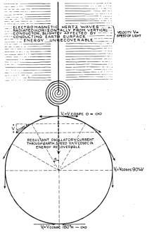
This
is the circuit energizing the antenna.
As the vibratory energy flows, two things happen: There is electromagnetic energy radiated and
a current passes into the earth. The
first goes out in the form of rays, which have definite properties. These rays propagate with the velocity of
light, 300,000 kilometers per second.
This energy is exactly like a hot stove. If you will imagine that the cylinder antenna is hot—and indeed
it is heated by the current—it would radiate out energy of exactly the same
kind as it does now. If the system is
applied in the sense I want to apply it, this energy is absolutely lost, in all
cases most of it is lost. While this
electromagnetic energy throbs, a current passes into the globe.
Now, there is a vast difference between these two, the electromagnetic and current energies. That energy which goes out in the form of rays, is, as I have indicated here, unrecoverable, hopelessly lost. You can operate a little instrument by catching a billionth part of it but, except this, all goes out into space never to return. This other energy, however, of the current in the globe, is stored and completely recoverable. Theoretically, it does not take much effort to maintain the earth in electrical vibration. I have, in fact, worked out a plant of 10,000 horsepower which would operate with no bigger loss than 1 percent of the whole power applied; that is, with the exception of the frictional energy that is consumed in the rotation of the engines and the heating of the conductors, I would not lose more than 1 percent. In other words, if I have a 10,000 horsepower plant, it would take only 100 horsepower to keep the earth vibrating so long as there is no energy taken out at any other place. [NT on AC, p. 140]
If Tesla
was right, low frequency wireless communications can be accomplished by the
production of either electromagnetic radiation in the form of space wave
induced ground currents and an accompanying electromagnetic wave called the Norton surface wave, or the production of a pulsed magnetic
field, high energy plasma phenomena, and ground currents at the transmitter,
resulting in an accompanying trapped surface-wave bearing a resemblance to the
Zenneck surface wave.
This is a
low frequency transverse magnetic surface wave that travels along the interface
between the ground and the air, in which the propagating energy does not
radiate into space but is concentrated near the guiding surface. These waves do not contribute significantly
to the field produced by a conventional dipole or quarter-wave radiator, however
they can be strongly excited by a quarter-wave helical resonator positioned
within a resonant cavity. [Corum & Corum]
To once
again to quote Tesla,
From my circuit you can get either electromagnetic waves, 90
percent of electromagnetic waves if you like, and 10 percent in the current
energy that passes through the earth. Or, you can reverse the process and get
10 percent of the energy in electromagnetic waves and 90 percent in energy of
the current that passes through the earth.
It is just like this: I have invented a knife. The knife can cut with the
sharp edge. I tell the man who applies my invention, you must cut with
the sharp edge. I know perfectly well you can cut butter with the blunt
edge, but my knife is not intended for this. You must not make the
antenna give off 90 percent in electromagnetic and 10 percent in current waves,
because the electromagnetic waves are lost by the time you are a few arcs
around the planet, while the current travels to the uttermost distance of the
globe and can be recovered.
This view, by the way, is now confirmed. Note, for instance, the
mathematical treatise of Sommerfeld, ["Propagation of Waves in Wireless
Telegraphy," Arnold N. Sommerfeld, Ann. Phys. (Leipzig), 28, 1909, pp.
665-737.] who shows that my theory is correct, that I was right in my
explanations of the phenomena, and that the profession was completely
misled. This is the reason why these followers of mine in high frequency
currents have made a mistake. They wanted to make high frequency
alternators of 200,000 cycles with the idea that they would produce
electromagnetic waves, 90 percent in electromagnetic waves and the rest in
current energy. I only used low alternations, and I produced 90
percent in current energy and only 10 percent in electromagnetic waves, which
are wasted, and that is why I got my results." [Nikola Tesla
On His Work With Alternating Currents and Their Application to Wireless
Telegraphy, Telephony and Transmission of Power; see also A
Comparison of Tesla and Marconi Low Frequency Wireless Systems]
Appendix
Antenna Theory and Impedance
Matching
A radiating electromagnetic field
is due to a collection of charged particles, specifically electrons,
oscillating in an electrical conductor.
Such a conductor comprises a radio-wave launching structure. The charge
is forced into oscillation by the injection of electrical energy from a source
such as a battery or electrical generator. The injection process involves
impedance matching of the energy source and the launching structure, as well as
the transmission line that connects the two. While the true structure of
the electron is not known, it is viewed as being a small sphere with an
electrical charge evenly distributed over its surface. Along with the charge is an electric field
known as the Coulomb field that points outward from the electron in all
directions. When in set into motion, an
electron becomes surrounded by a circular magnetic field. When an electron is made to accelerate or
decelerate an additional electric field component called the dynamic electric
field arises. The dynamic electric
field component itself can be regarded as being comprised of two additional
field components. The overall field
intensity of these additional field components is their vector sum. The first, the radiation field component,
exists in phase with the magnetic field.
This means that the radiation field increases in intensity
simultaneously with the increase of intensity of the magnetic field. The other dynamic electric field component,
the induction field, is out of phase with the magnetic field, lagging behind it
by a phase angle of 90deg.
In oscillation this energy is traded back and forth between
its inductive [magnetic] and its capacitive [electrostatic] energy storage
components. Periodic movement of the charge sets up a sinusoidal E-field
and cosinusoidal H-field. The H component carries the magnetic energy and
the E component carries the electrostatic energy. During the oscillation
of the charge/field, it's stored energy alternates between a magnetic peak and
an electrostatic peak. The oscillation occurs at a fixed frequency primarily
dependent upon the geometry of the launching structure and to a lesser extent
the proximity of any surrounding objects. The process of dipole radiation
also involves impedance matching, in this case that of the dipole oscillator to
the impedance of free space, which is E/H = 377 ohms. The E/H impedance
ratio of the dipole field is determined by the magnitude of source charge and
distance through which it oscillates. The EM wave travels outwards and,
encountering the free-space impedance, some portion of the radiated power is
reflected back to the launching structure due to more or less of an impedance
mismatch. The remainder continues to radiate away from the antenna, escaping
in the form of electromagnetic Hertz waves [see “Why an Antenna
Radiates,” http://www.abelian.demon.co.uk/tesla-notes/030802.html,
Teaching Electromagnetism Using Advanced
Technologies].
Capacity
of an Elevated Sphere
“The self-capacitance of
a spherical conductor is proportional to its radius, and is 111 pF or
micro-micro farads per metre of radius.” [Henry Bradford]
Tesla’s Colorado Springs
investigations led him to the conclusion that the capacitance of an elevated
terminal is not constant, but increases with elevation.
Exactly as mechanics and engineers
have taken it for granted that the pliability of the spring remains the same,
no matter how it be placed or used, so electricians and physicists have assumed
that the electrostatic capacity of a conducting body, say of a metallic sphere,
which is frequently used in experiments, remains a fixed and unalterable
quantity, and many scientific results of the greatest importance are dependent
on this assumption. Now, I have discovered
that this capacity is not fixed and unalterable at all. On the contrary,
it is susceptible to great changes, so that under certain conditions it may
amount to many times its theoretical value, or may eventually be smaller. . . .
Continuing the investigation of this astonishing phenomenon I observed that the
capacity varied with the elevation of the conducting surface above the ground
and I soon ascertained the law of this variation. The capacity increased as the conducting surface was elevated, in
open space, from one-half to three-quarters of 1 percent per foot of
elevation. In buildings, however, or
near large structures, this increase often amounted to 50 percent per foot of
elevation, . . . [38b]
Ground Current Behavior
Tesla speculated about the
behavior of the ground currents involved in the operation of the system.
There is another
difference. The electromagnetic energy
travels with the speed of light, but see how the current flows. At the first moment, this current propagates
exactly like the shadow of the moon at the earth's surface. It starts with infinite velocity from that
point, but its speed rapidly diminishes; it flows slower and slower until it
reaches the equator, 6,000 miles from the transmitter. At that point, the current flows with the
speed of light—that is, 300,000 kilometers per second. But, if you consider the resultant current
through the globe along the axis of symmetry of propagation, the resultant
current flows continuously with the same velocity of light.
Whether this current passing through the
center of the earth to the opposite side is real, or whether it is merely an
effect of these surface currents, makes absolutely no difference. To understand the concept, one must imagine
that the current from the transmitter flows straight to the opposite point of
the globe.
There is where I answer the attacks which
have been made on me. For instance, Dr.
Pupin has ridiculed the Tesla system.
He says,
"The energy goes only in all
directions."
It
does not. It goes only in one
direction. He is deceived by the size
and shape of the earth. Looking at the
horizon, he imagines how the currents flow in all directions, but if he would
only for a moment think that this earth is like a copper wire and the transmitter
on the top of the same, he would immediately realize that the current only
flows along the axis of the propagation.
The mode of propagation can be expressed by a very simple mathematical law, which is, the current at any point flows with a velocity proportionate to the cosecant of the angle which a radius from that point includes with the axis of symmetry of wave propagation. At the transmitter, the cosecant is infinite; therefore, the velocity is infinite. At a distance of 6,000 miles, the cosecant is unity; therefore, the velocity is equal to that of light. This law I have expressed in a patent by the statement that the projections of all zones on the axis of symmetry are of the same length, which means, in other words, as is known from rules of trigonometry, that the areas of all the zones must also be equal. It says that although the waves travel with different velocities from point to point, nevertheless each half wave always includes the same area. This is a simple law, not unlike the one which has been expressed by Kepler with reference to the areas swept over by the radii vectors.
I hope that I have been clear in this
exposition—in bringing to your attention that what I show here is the system of
the day, and is my system—only the radio engineers use my apparatus to produce
too much of this electromagnetic energy here, instead of concentrating all
their attention on designing an apparatus which will impress a current upon the
earth and not waste the power of the plant in an uneconomical process. [NTAC]
Nikola Tesla’s Priority in the
Invention of Radio
As stated in the book Tesla
- Master of Lightning, “The question of who invented radio, and when, and
what defines the invention, have sparked fierce debates that still
continue.” Re-reading the chapter in
question I found one assertion that perhaps should be revised. On page 66 one of the authors writes,
"Tesla, in fact, thought that Hertz had misinterpreted the results of his
experiment. Tesla believed that radio
signals were induced by earth currents, not air waves."
On the contrary, Tesla fully acknowledged the existence of
“air waves.”
It was a perfectly
well-established fact that a [dipole] circuit, traversed by a periodic current,
emitted some kind of space waves. . . .
Tesla goes on to state,
As regards signaling without wires, the application of these radiations for the purpose was quite obvious. When Dr. Hertz was asked whether such a system would be of practical value, he did not think so, and he was correct in his forecast. The best that might have been expected was a method of communication similar to the heliographic and subject to the same or even greater limitations. [The True Wireless]
Needless to say, Tesla was somewhat off the mark with that
prediction.
His fundamental disagreement lay in the model used to
describe the physical process that takes place within the propagating
medium. Hertz had described this as
transversal vibrations in the ether.
Tesla’s model differed from Hertz’s in that propagation is described as
being by compression and rarefaction of the propagating medium, similar to
acoustic waves traveling through gas.
The assumption of the Maxwellian
ether was thought necessary to explain the propagation of light by transverse
vibrations, which can only occur in a solid.
So fascinating was this theory that even at present it has many
supporters, despite the manifest impossibility of a medium, perfectly mobile
and tenuous to a degree inconceivable, and yet extremely rigid, like
steel. As a result some illusionary
ideas have been formed and various phenomena erroneously interpreted. The so-called Hertz waves are still
considered a reality proving that light is electrical in its nature, and also
that the ether is capable of transmitting transverse vibration of frequencies
however low. This view has become
untenable since I showed that the universal medium is a gaseous body in
which only longitudinal pulses can be propagated, involving alternating
compressions and expansions similar to those produced by sound waves in the air. Thus, a wireless transmitter does not emit
Hertz waves which are a myth, but sound waves in the ether, behaving in every
respect like those in the air, except that, owing to the great elastic force
and extremely small density of the medium, their speed is that of light. [Pioneer
Radio Engineer Gives Views on Power, New York Herald Tribune, September 11, 1932]
In our
present physical model the closest analogous description we have to this
“universal medium” is plasma—often referred to as the fourth state of
matter. It has been suggested that
plasma should be called the first state of matter, as it is plasma of which
about 99% of the known universe is composed. [Plasma
Dictionary: Plasma]
Tesla’s Early Wireless Work
It is a little known
fact that Tesla used his high voltage resonance transformer—the Tesla coil—in
radio wave propagation experiments. In
his words,
The popular impression is that my wireless work was begun in 1893, but as a matter of fact I spent the two preceding years in investigations, employing forms of apparatus, some of which were almost like those of today. . . .[The True Wireless]
After a while he began
to favor another technique that he called the “air-ground method.” He used the same basic apparatus, however
instead of using electromagnetic space waves, the energy is carried by
conduction of electrical currents through the earth and accompanying surface
waves. For a type-1 transmission system
the ‘return’ path closing the circuit is an electrical current flow established
between two elevated terminals, one belonging to the transmitter and the other
the receiver. These consist of true
conduction currents flowing through plasma and also electrostatic induction. The Wardenclyffe plant was designed to
operate on this principle.
. . . It was clear to me from the very start that the successful consummation could only be brought about by a number of radical improvements. Suitable high frequency generators and electrical oscillators had first to be produced. [This work is discussed above.] The energy of these had to be transformed in effective transmitters and collected at a distance in proper receivers. Such a system would be manifestly circumscribed in its usefulness if all extraneous interference were not prevented and exclusiveness secured. In time, however, I recognized that devices of this kind, to be most effective and efficient, should be designed with due regard to the physical properties of this planet and the electrical conditions obtaining on the same. . . . [The True Wireless]
Tesla’s pioneering contribution to radio technology was a
reworking of the primitive Hertz spark-gap transmitter; introduction of the
coupled tuned circuit with the energy storage capacitor and discharger repositioned
to the primary side of the transformer. [Kenneth and James Corum] This is the classic Tesla coil configuration, with primary and
secondary circuits tuned to vibrate in harmony. These modifications allowed significantly higher levels of radio-frequency
energy to be concentrated into a damped or partially damped wave, and
ultimately a practically undamped wave. Some historians credit Reginald
Fessenden in 1900 for making these improvements. Others credit Adolph Slaby.
Still others say it was Ferdinand Braun, in a hastily improvised
demonstration performed in September 1898.
Braun, together with Marconi, received the Nobel Prize in physics for
this replication of Tesla’s discovery.
Tesla’s circuit diagram from the 1891 U.S. Patent
"System of Electric Lighting" shows an energy
storage capacitor and discharger on the primary side of a radio-frequency
power-supply transformer. This is the
first-ever disclosure of a practical high power radio-frequency power
supply. It represents a device that is
capable of exciting an antenna to emit powerful electromagnetic radiation.
Actually,
it was Nikola Tesla who first revealed the basic techniques for improving
transmitter performance. He did this in
a series of U.S. patents, starting with his "System of Electric
Lighting," Patent No. 454,622, dated June 23, 1891, the accompanying
drawing of which clearly shows an energy storage capacitor and a discharge
device on the primary side of a resonance transformer. In1893 at a public
meeting of the National Electric Light Association in St. Louis, this
radio-frequency power supply circuit was used to demonstrate the world's first
practical radio transmitter.
"In the transmitter group on one side of the stage was
a 5-kva high-voltage pole-type oil-filled distribution transformer connected to
a condenser bank of leyden jars, a spark gap, a [Tesla] coil, and a wire
running up to the ceiling.
"In the receiver group at the other side of the stage was an identical
wire hanging from the ceiling, a duplicate condenser bank of Leyden jars and
coil—but instead of the spark gap, there was a Geissler tube that would light
up like a modern fluorescent lamp bulb when voltage was applied. There
were no interconnecting wires between transmitter and receiver." [Tesla-Man
Out of Time]
His patent
"Means for Generating Electric Currents" No. 514,168 of February 6,
1894 describes a variation of the 1891 circuit. Between September 15,
1896 and November 18, 1898 no fewer than 17 patents were granted to Tesla for
apparatus and methods directly related to the production of high power
radio-frequency electrical currents. It was during that same period, on
September 2, 1897, that Tesla filed his first application which was directly
related to wireless transmission and reception, resulting in two patents that
were subsequently issued as System of . . ." and "Apparatus for
Transmission of Electrical Energy," dated March 20 and May 15, 1900
respectively. On July 1, 1898 another wireless-related application was
filed for the radio-controlled boat resulting in the patent, "Method of
and Apparatus for Controlling Mechanism of Moving Vessels or Vehicles"
issued November 8, 1898. He also developed receivers incorporating two tuned
circuits. Between 1898 and 1903 Tesla
received 10 U.S. patents covering his work in this area.
In 1904
Marconi got his own patent, declaring principles that Tesla had developed. The issue of patent infringement by Marconi
was addressed in a lawsuit brought by Tesla in 1915. Nothing significant resulted from this litigation and shortly
thereafter the Marconi Wireless Telegraph Company of America itself sued
the United States for alleged damages resulting from the use of wireless during
WWI. In response, a 1935 ruling by the
United States Court of Claims essentially invalidated the fundamental Marconi
patent. It was decided that the basic
apparatus associated with radio communications had, in fact, been anticipated
by Tesla. The U.S. Supreme Court affirmed this finding on June 21,
1943. The following definition of radio emerged as a result of this case:
A radio communication system
requires two tuned circuits each at the transmitter and receiver, all four
tuned to the same frequency. [Marconi Wireless
Telegraphy Company vs. United States]
Additional
reading:
- “Marconi
Wireless Telegraphy Company of America v United States,” 320 U.S. 1. Nos. 369, 373. Argued April 9-12,
1943. Decided June 21, 1943
- Anderson, L.I., “Priority in the Invention of
Radio: Tesla vs. Marconi,” Antique Wireless Association Monograph No. 4,
March, 1980.
- Anderson,
L.I., “John Stone Stone on Nikola Tesla's Priority in Radio and Continuous-Wave
Radiofrequency Apparatus,” The A.W.A. (Antique Wireless Association)
Review, Vol. 1, 1986, pp. 18-41.
- Wunsch,
A.D., "Misreading the
Supreme Court,” Antenna, Volume 11 No. 1, Nov. 1998,
Society for the History of Technology
- Brand, W.E.,”Rereading the
Supreme Court: Tesla's Invention of Radio,” Antenna, Volume 11 No. 2, May 1998,
Society for the History of Technology
Investigation of Tesla-Type Wireless Propagation [mathematical modeling and physical validation]
After all this there is still the
unanswered question, exactly how does the Tesla system work? It appears that early on Tesla himself was
somewhat unsure. This especially seems
to be the case when construction of the Wardenclyffe facility began. If the laws of physics, and operational
parameters of his apparatus were known with mathematical certainty he would not
have made the critical design errors alluded to in a 1903 letter to J.P.
Morgan. [Wardenclyffe
and the World System : The history and design of Nikola Tesla’s wireless
telecommunications facility on Eastern Long Island]
He made observations and collected data,
but given the primitive state of plasma physics at the time, it would have been
difficult if not impossible for him to properly explain what was actually
taking place. [See The
Generation of Plasma Waves at the Earth's Surface for Telecommunications Purposes.]
Employ mathematical
analysis.
Know the difference
between facts and assumptions.
Exhibit a balance between theory and experiment.
Validate the technology
through testing.
Present day electromagnetic theory based upon Maxwell’s
Equations. Undamped wave equation,
Laplace-Operator can be decomposed into two parts, scalar and vector.
[“Electric Scalar Waves – Review to Meyl’s Experiment,” “Elektrische
Skalarwellen” - Review zum Meyl'schen Experiment, André Waser. See also Nikola
Tesla’s Wireless Systems.]
Negative solution to Maxwell’s Equations allows creation of
a magnetic field without current flow in wire.
[Maurice Hately & Fathl
Kabbary, 1995
Longitudinal
Waves Waves where
the variation of the field is partially or totally in the direction of
propagation (parallel to wavennumber, k [a vector]. Examples include sound waves and Langmuir waves. Contrasted with transverse waves, where the
variation is perpendicular to the direction of propagation, such as light
waves.
Plasma Known as the "Fourth State of Matter", a plasma is a
substance in which many of the atoms or molecules are effectively ionized,
allowing charges to flow freely. Since
some 99% of the known universe is in the plasma state and has been since the
Big Bang, plasmas might be considered the First State of Matter. Plasmas have unique physics compared to
solids, liquids, and gases; although plasmas are often treated as extremely hot
gases, this is often incorrect.
Examples of plasmas include the sun, fluorescent light bulbs and other
gas-discharge tubes, very hot flames, much of interplanetary, interstellar, and
intergalactic space, the earth's ionosphere, parts of the atmosphere around
lightning discharges, laser-produced plasmas and plasmas produced for magnetic
confinement fusion. Types of plasmas
include - Astrophysical, Collisionless, Cylindrical, Electrostatically Neutral,
Inhomogeneous, Intergalactic, Interstellar, Magnetized, Nonneutral, Nonthermal,
Partially Ionized, Relativistic, Solid State, Strongly Coupled, Thermal,
Unmagnetized, Vlasov and more.
Plasma
Wave A disturbance
of a plasma away from equilibrium, involving oscillations of the plasma's
constituent particles and/or the electromagnetic field. Plasma waves can
propagate from one point in the plasma to another without net motion of the
plasma. Terms used to describe the many kinds of waves in plasmas include:
Alfven, Circularly Polarized, Cold Plasma, Drift, Electromagnetic,
Electron-Cyclotron, Electron Plasma, Electrostatic, Electrostatic Ion,
Electrostatic Ion Cyclotron, Evanescent Extraordinary, Ion-Acoustic, Ion
Cyclotron, Ion Plasma, Ion Sound, Langmuir, Left Circularly Polarized, Light,
Longitudinal, Lower Hybrid, Magnetohydrodynamic (MHD), Magnetosonic, Negative
Energy, Nonlinear, Ordinary, Parallel, Perpendicular, Plane, Radio, Right
Circularly Polarized, Shock, Space-Charge, Transverse Travelling, Unmagnetized,
Upper-Hybrid, Vlasov, Whistler.
Plasma Oscillations Class of electrostatic
oscillations which occur at/near the plasma frequency (see entry) and involve
oscillations in the plasma charge densities. These modes are also known as
Langmuir oscillations or Langmuir waves; in Stix's _Waves in Plasmas_ they are
more properly called Langmuir-Tonks Plasma Oscillations.
Ion
acoustic wave A
longitudinal compression wave in the ion density of a plasma. For more
information see (e.g.) Stix, Thomas Howard. _Waves in Plasmas_, American
Institute of Physics, New York, 1992.
Soliton Solitons, or solitary waves, are
stable, shape-preserving and localized solutions of nonlinear classical field
equations, where the nonlinearity opposes the natural tendency of the solution
to disperse. They were first discovered in water waves, and there are several
hydrodynamic examples, including tidal waves. Solitons also occur in plasmas.
One example is the ion-acoustic soliton, which is like a plasma ``sound'' wave;
another is the Langmuir soliton, describing a type of large amplitude
(nonlinear) electron oscillations. Solitons are of interest for optical fiber
communications, where it has been proposed to use optical envelope solitons as
information carriers in fiber optic networks, since the natural nonlinearity of
the optical fiber may balance the dispersion and enable the soliton to maintain
its shape over large distances.]
Note: The C/S structure
resembles a “conventional” antenna, with a subsequent shift to the prototypical
launching structure at Wardenclyffe.
Possible side effects
related to system operation:
Ozone production
Static electricity
effects
Electrostatic induction
is a better term than dielectric displacement current.
Oscillating dipoles in
dielectric medium
What dipoles in the
classical vacuum?
Phase conjugation
Phase velocity
Spread spectrum
frequency division multiplexing
Channels at 7.8 Hz
increments [Corum & Corum]
Top-turn primary of
large C/S oscillator pulse-driven by alternator to produce ELF component.
(Corum & Corum)
While at C/S Tesla considered
or investigated at least 125 different variations of receiver design. [Tesla's
Synchronized Receiving Apparatus]
N.T. Museum for information on patents-not-granted
application filings, ca. 1900-1902
High-speed break or
circuit controller
RF alternator
High-voltage mechanical rectifier
High power solid-state
switch and a signal generator
More on Tesla coils . .
.
Master oscillator tuning
corresponds with resonant frequency of the top loaded resonator.
The secondary winding
length should be approximately ____% of the operating frequency wavelength.
Analyze C/S data for
secondary length / resonator frequency relationship
Tesla said the transformer should be tuned to avoid the
beat.
Transformer increases
voltage, and introduces series inductance.
Does this relate to the development of a wave complex?
Is this for an isotropic
capacitance, i.e., the smaller of two concentric conducting spheres with larger
sphere taken out to infinity?
Is this an accurate
statement for real-world conditions?
Influence of elevation upon capacity?
Influence of environment in general upon
capacity?
Attempt to
mathematically describe what Tesla was claiming about his system.
Precise performance data
would be useful in formulating a solution.
Formulate a
boundary-value solution for the helical resonator.
Helical resonator is not
an antenna loading coil.
The earth as a transmission
line
Validate antenna theory,
i.e. real-world model of the production of electromagnetic radiation, without
speaking of the isotropic radiator as if it actually exists in the real
world. Or does it exist?
Electrostatic induction between elevated capacitance and
Earth’s surface. [Wasser]
Electrostatic induction between elevated capacitances.
Magnetic coupling or mutual induction between distant
helical resonators.
Capture area exceeds physical dimensions of receiving
structure & reciprocity with launching structure.
Near field or quasi-near field conditions throughout global
network.
Mathematical description
of vertical dipole antenna in free space?
Mathematical description
of Marconi antenna?
Mathematical description
of type-one Tesla antenna?
Mathematical description
of type-two Tesla antenna?
Are all four
electrically equivalent?
Follow the energy: If the Marconi antenna differs from the
Tesla antenna in the production of electromagnetic radiation, were does the
energy go in the latter case, i.e., how is the energy dissipated in the Tesla
systems?
Incorporate multiple single terminal vacuum tubes in
construction of the elevated terminals, as disclosed in teleforce disclosure.
Derive some impressions from the “Oscillator Shuttle Circuit” patent
disclosure.
Treating the Marconi antenna as the equivalent of a
half-wave dipole, the electric field energy and the magnetic field energy are introduced
into the field medium in time-phase with each other. The excitation of the medium by the antenna develops a “forced
propagation mode,” degenerating into “natural mode propagation” with energy
dissipation taking place over an initial range of transmission. In contrast, the Tesla launching structure
is so configured that . . . the
electric and magnetic fields are set up in quadrature phase, i.e., a 90deg
phase shift as compared to dipole, corresponding to the natural propagation
mode of the field medium. [Gieskieng Antenna, An Antenna With
Anomalous Radiation Properties, Harold Aspden, 1987, 1998]
“Slaby improved the equipment, as transmitter served now a
spark coil, whose spark gap did not lie in the transmitting antenna - as with
Marconi -, but in a circle coupled inductively with the circuit of
antennas. Independently of Slaby the
physicist Ferdinand Braun in Strasbourg worked on radio systems. It was first, that had really understood,
what with Marconi‘s devices electrically took place. From theoretical considerations Braun came to the conclusion to couple
the spark gap with the transmitter inductively (resonant circuit, 1898) and
also the coherer inductively to the antenna to couple. For this basic concept
Braun received the Nobel Prize, together with Marconi.”
Search phrases:
dipole antenna
"antenna theory" physics
model
“NEC software”
"EH Antenna"
Search results:
NEC software is based on a solution of Maxwell's
Equations. For wire types of
structures, it solves Maxwell's Equations using the Electric Field Integral
Equation. For surface types of
structures, it solves them using the Magnetic Field Integral Equation. The program is capable of solving
complicated structures. Its accuracy
and limitations are well documented in the scientific literature, and it can
easily solve a fairly simple antenna structure.
“Maxwell's Equations are considered an exact solution for
electromagnetic radiation.” (?)
"The phasing network aligns the relative phase between
the current and the voltage of the radio frequency power signal so that the
H-field component of the corresponding electromagnetic signal is nominally in
time phase with the E-field component".
This is exactly what happens in every antenna and is called
the Poynting vector.
If the E and H fields are not in time alignment, the antenna
will not radiate.” (?)
The power feeding your antenna is going to one or more of
the following places:
- Radiation from the antenna
- Power dissipation in the antenna
- Power dissipation in the matching network
- Radiation from the coax
- Power dissipation in the coax
- Power dissipation in the transmitter (most people don't realize
that transmitters can dissipate power that is not radiated by the antenna)
You will need to do a carefully controlled set of
experiments to determine where the power is going in your setup. E-H Antenna Simulation in NEC
End Notes
1. Norton surface wave The ground-wave component of a space wave resulting from refraction of a portion of the reflected-wave component at the Earth-atmosphere interface and induction of electrical currents in the ground. Upon reflection from the Earth's surface the reflected wave undergoes a 180deg phase reversal. When both transmitting and receiving antennas are on, or close to, the ground, and the distance between them becomes great, the direct and reflected components tend to cancel out, and the resulting field intensity is principally that of the surface wave. Because part of its energy is absorbed by the ground, the electrical intensity of the surface wave is attenuated at a much greater rate than inversely as the distance. It is the conductivity of the underlying terrain that determines the attenuation of the surface-wave field intensity as a function of distance. The ground currents of a vertically polarized surface wave do not short-circuit a given electric field but rather serve to restore part of the used energy to the following field. The better the conducting surface layer, the more energy returned and the less energy absorbed.
2. Zenneck surface wave A low frequency transverse magnetic surface wave that travels along the interface between the ground and the air, in which the propagating energy does not radiate into space but is concentrated near the guiding surface. These waves do not contribute significantly to the field produced by a conventional dipole or quarter-wave radiator, however they can be strongly excited by a grounded quarter-wave helical resonator. See slow-wave helical resonator and magnifying transmitter.
Geometry for Zenneck wave propagation.

The complex longitudinal propagation phase constant along the Earth's surface.
Zenneck wave field strength decrease for around-the-world propagation as a
function of frequency in kHz. [*]
·
Corum, K. L.
and J. F. Corum, "The Zenneck Surface Wave," Appendix II of
"Nikola Tesla, Lightning Observations, and Stationary Waves," 1994.
Kirchoff's Laws and their application to direct current (DC) circuits
Kirchoff's Laws
describe the behavior of electrical currents flowing in direct current (DC)
electrical circuits. DC circuits
consist of one or more voltage sources connected to one or more of the
following: resistors, capacitors and inductors.
A simple DC
circuit consisting of a DC source and a single resistor
Kirchoff's
1st Law states that the current flowing into a junction in a circuit (or node)
must equal the current flowing out of the junction. This law is a direct
consequence of the conservation of charge. Since no charge can be lost in
the junction, any charge that flows in must ultimately flow out.
Kirchoff's 1st Law can be remembered as the rule that uses nodes to study the
flow of current around a circuit.
Kirchoff's
2nd Law This law states that for any closed loop path around a circuit the sum
of the voltage gains and voltage drops equals zero. In the circuit shown,
there is a voltage gain for each electron traveling through the voltage source
(symbolized by ) and a voltage drop across the resistor ( iR). Applying
Kirchoff's law:

Note that this result has the same form as Ohm's law:
![]()
Kirchoff's 2nd Law is based on the principle of conservation of energy. No
energy can be lost from or gained by the circuit, so the net voltage change
must be 0. Kirchoff's 2nd Law can be remembered as the rule that uses loops to
study the flow of current around a circuit. [Source: http://www.scientia.org/cadonline/Physics/circuits/kirchoff.ASP,
see also http://www.scientia.org/cadonline/Physics/circuits/home.ASP.]

A simple RC circuit consisting of a
DC source, a resistor and a capacitor
To solve the circuit when it is charging , Kirchoff's second
law is applied:
![]()
Both i and q are time dependent, so another linearly
independent equation is needed to solve the circuit. This equation shows the
relation between i and q :
![]()
A way to understand this equation is to consider a plot of
q(t) vs. t. The slope of the curve at the point [t,q(t)] equals the current
i(t) at time t .
Solving (1) and (2) requires an understanding of
differential and integral calculus, so only the solutions are given:
Plots of these functions are shown. Note that the charge of the
capacitor increases from an initial value of 0 to a maximum value of C.
This increase is the reason why the RC circuit is said to be charging. Simultaneously,
the current flow decreases from an initial value of -
/R
to a minimum value of 0. Current ceases to flow when the capacitor is fully
charged.
The RC circuit can be discharged only after it has been
charged. In the following example, it
is assumed that the capacitor is fully charged. Therefore, just before the switch is thrown to disconnect the
power supply,
From Kirchoff's second rule,
Again, the relation between i and q is necessary to solve,
Working through the calculus,
Plots of these functions are shown . Note that the charge of
the capacitor decreases from an initial value of -/R
to a minimum value of 0. This decrease is the reason the RC circuit is said to
be discharging. Simultaneously, the current flows with maximum magnitude
initially C
(but in the opposite direction as in the charging circuit) to a final value of
0. Current ceases to flow when the capacitor has been fully discharged.
[See also:
http://www.scientia.org/cadonline/Physics/circuits/branch.ASP
http://www.scientia.org/cadonline/Physics/circuits/loop.ASP
http://www.scientia.org/cadonline/Physics/electrostatics/fields.ASP
http://www.scientia.org/cadonline/Physics/electrostatics/potential.ASP
http://www.scientia.org/cadonline/Physics/electrostatics/dipole.ASP
http://www.scientia.org/cadonline/Physics/electromagnet/fields.ASP
http://www.scientia.org/cadonline/Physics/electromagnet/biot.ASP
Kirchoff's Laws and their application to alternating current
(AC) circuits
Alternating currents or AC currents regularly
change their direction of flow. The current and voltage obey equations that
involve the sine function and that are derived through the use of calculus:
The term
Since sine waves are symmetrical, calculating the average
current or voltage over one complete cycle yields an answer of 0. Since this
quantity is meaningless, when considering the current of an AC circuit, a
quantity known the root-mean-square (rms) current is used. This quantity is
calculated to be
A similar quantity is used for voltage:
[Source: http://www.scientia.org/cadonline/Physics/capacitors/ac.asp]

Jan. 13, 2004
Greetings Gary:
I hope that some of the e-mail addresses
on this old list are still valid. A retired
radio man in Oregon recently asked me about Tesla's proposed system for
wireless transmission of power. As you
know, there is no easy answer to this question because there is so little clear
information about what Tesla was doing in this regard. The following is my reply. I am passing it along to you because I
thought it might be of general interest.
Perhaps someone would forward it to Margaret Cheney.
I have not attached the material referred
to, but I think you can follow the arguments without it. Most of the diagrams referred to are in my
article about Tesla in the February and May 1999 issues of the Old Timer's
Bulletin (OTB), published by the Antique Wireless Association. I hope that no one will take offence at some
of my criticism of other people's interpretations of Tesla's wireless work, and
I will not take offence at criticism of my views. . . .
. . . Since the mathematics would be very difficult, I believe
that the best approach would be a numerical computer analysis, tracing the
signal from the transmitter terminal and ground to the opposite end of the
Earth, and done from a few Hertz to about a megahertz. Since a good mathematical model of the
ionosphere and upper layers of the earth or ocean would be required, the same
analysis could be done for conventional LF and VLF radio transmitters for
comparison.
. . . My own rough analysis above leads me to believe that the
Tesla system would be hopelessly ineffective for wireless transmission of power
at the ultra-low Schumann resonance frequencies. If my numbers are correct, I cannot imagine what Tesla was
thinking of. Tesla was no fool, but he
may have been wrong about harnessing whole Earth resonance, if in fact that was
what he planned to do.
. . . I believe that radio waves and Tesla earth currents would
diminish with distance from their respective transmitters at roughly similar
rates.
Cheers,
Henry
- The discrepancy between Tesla’s
claims and the results of your calculations needs resolution.
- You’re right in suggesting that the
Tesla system is not the same as the radio system of today. Nevertheless, I believe the Tesla
system could be brought into service with very little modification to
present-day receiving equipment.
- No doubt Tesla himself thoroughly
investigated the effectiveness of such currents for wireless
telecommunications purposes. There
are some who believe the over-the-horizon “woodpecker” signals that
flooded portions of the HF spectrum between 1976 and the late 1980s were
the result of experiments along this line. The High Altitude Auroral Research Project (HAARP) may also
include research of this general nature.
- The basic Tesla system involves the
flow of alternating electrical currents through a closed circuit. While the development of radio waves
would certainly result from the current flowing through the earth between
two transmitter/receiver facility ground connections, I believe the signal
strength would be fairly consistent along entire distance between the two points.
